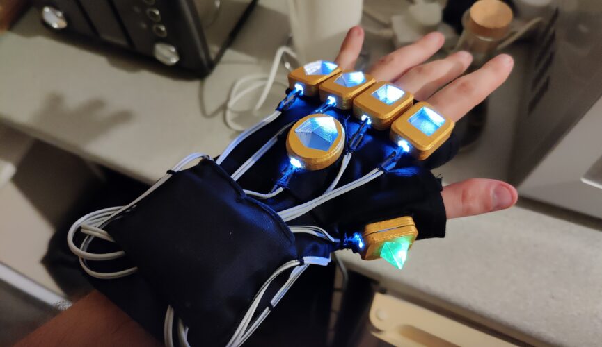
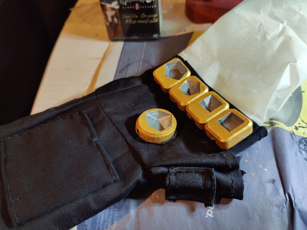
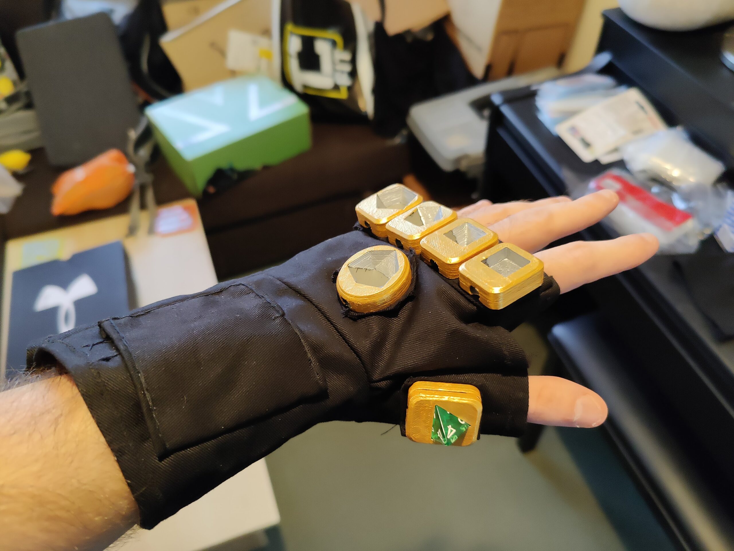
With the lighting circuit, dice mounts and base layer complete, it was time to bring them together. The first thing to do was to superglue the d4 into its mount, to avoid having to glue the two halves together later. Then I attached each mount to the relevant pad using superglue.
Used greaseproof paper to prevent any glue seeping through and sealing the wrap-around closedd4 mount attached
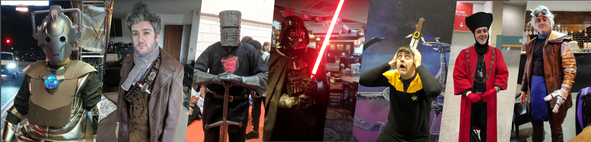
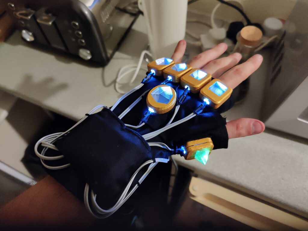
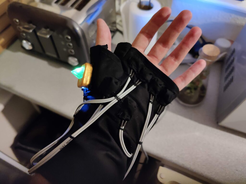
Attaching the circuit itself involved inserting the LEDs and sewing their cables in place. The tactile switches were sewn into their respective pockets, then the wires were fixed in position by sewing loops of thread.
LEDs with circuit board mountedTactile switches attached
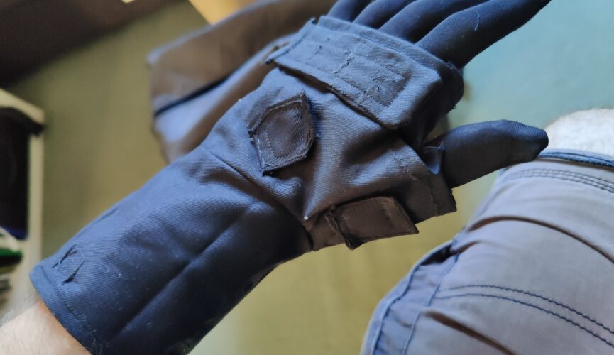
I threaded the power socket through a button hole so it could be accessed from the inside of the wrap-around.
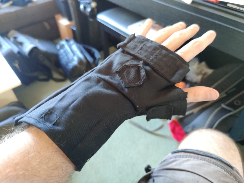
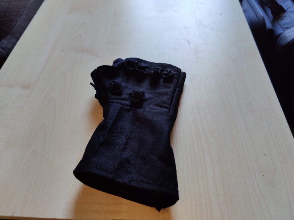
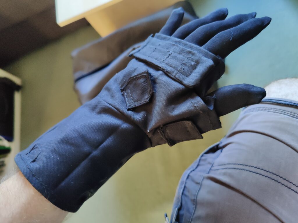
Gloves can be complicated, and my clothing design and manufacturing skills are limited. I had to work within what I could feasibly achieve, and having made a variation on an infinity gauntlet before (don’t ask) I decided to go with the approach I took last time: Use a standard glove to sew fingers onto, then sew that glove inside a wrap-around for the palm, which would essentially be a tube with an extra bit on the side for the thumb.
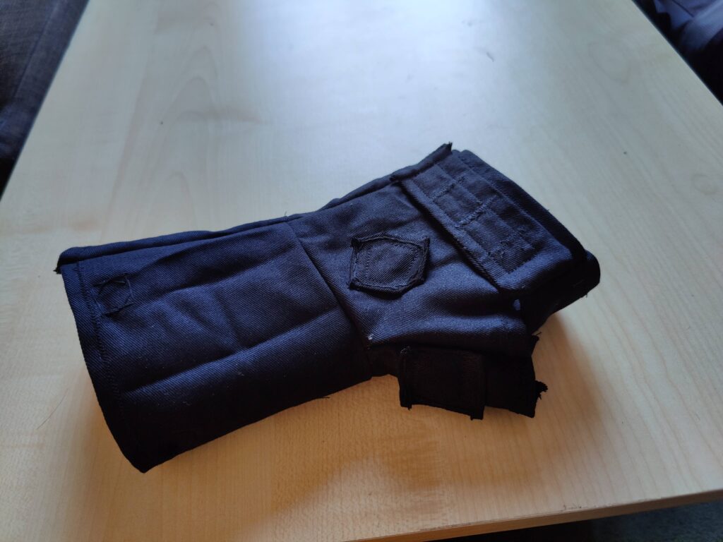
The wrap-around would consist of two layers:
An inner base layer, onto which the dice mounts would be glued and the circuit would be mounted (with hand sewing)
An outer layer, consisting of the actual visual design, with holes through which the mounts would protrude.
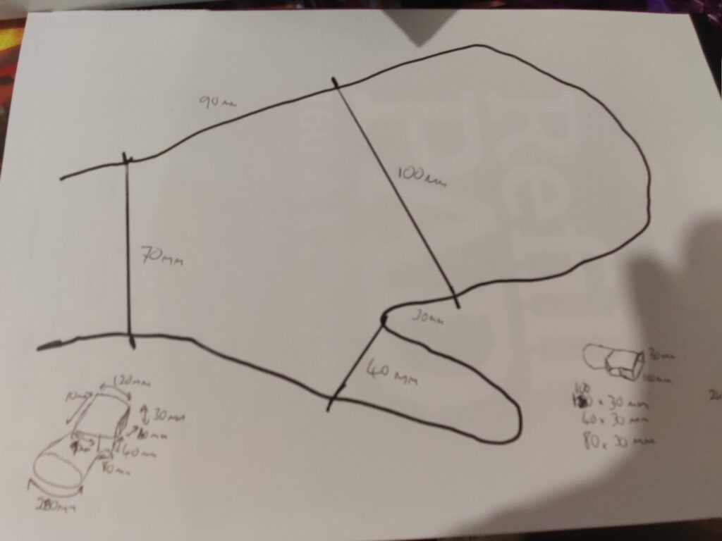
My approach to coming up with a pattern is very geometric, essentially approximate with a boxy design and hope the fabric’s tendency to curve will round it out. It’s also easier to think of a polyhedral net of flat faces rather than a more complex curved topology. The first step was, of course, to get measurements.
When in doubt, trace around it
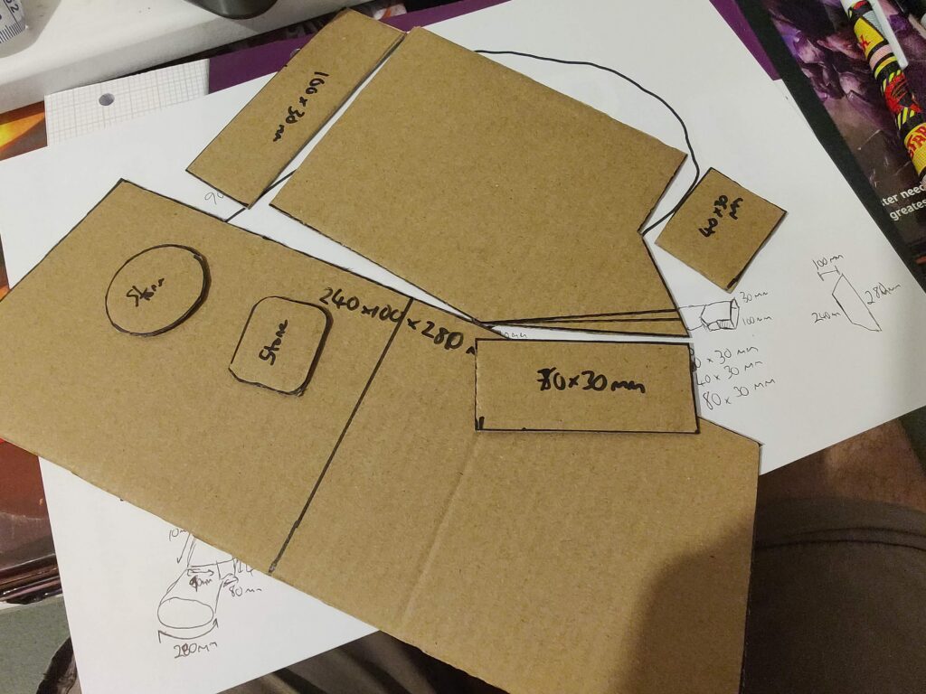
Pretty simple, trace around my left hand and use a ruler to roughly measure the notable lengths. Mark off where my knuckles and wrist were (roughly). Add a bit for ease of putting on/taking off, then create cardboard templates.
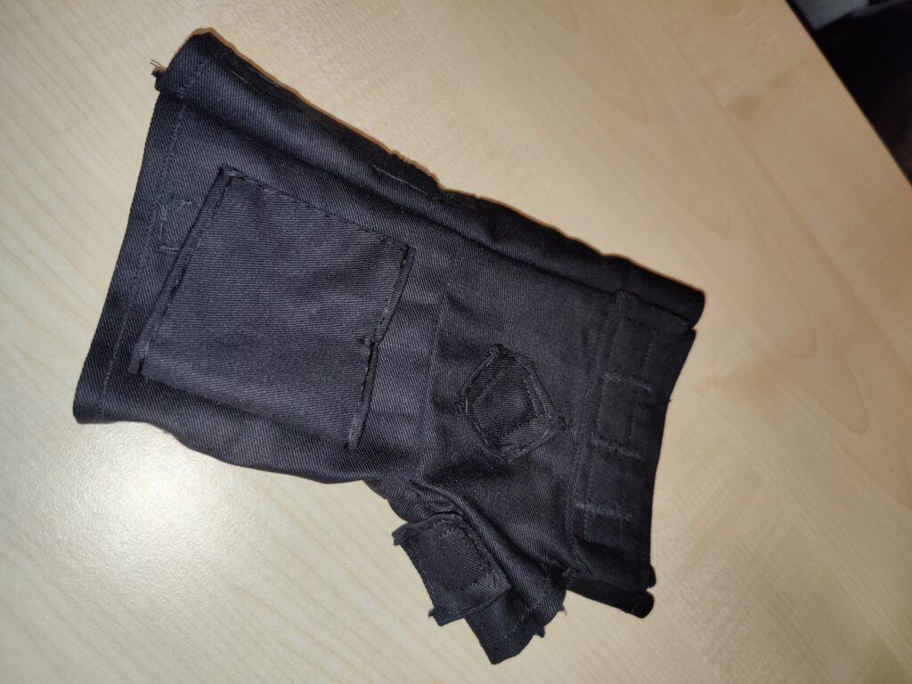
I also intended to add patches for the dice mounts, so I could be more exact when eventually attaching them.
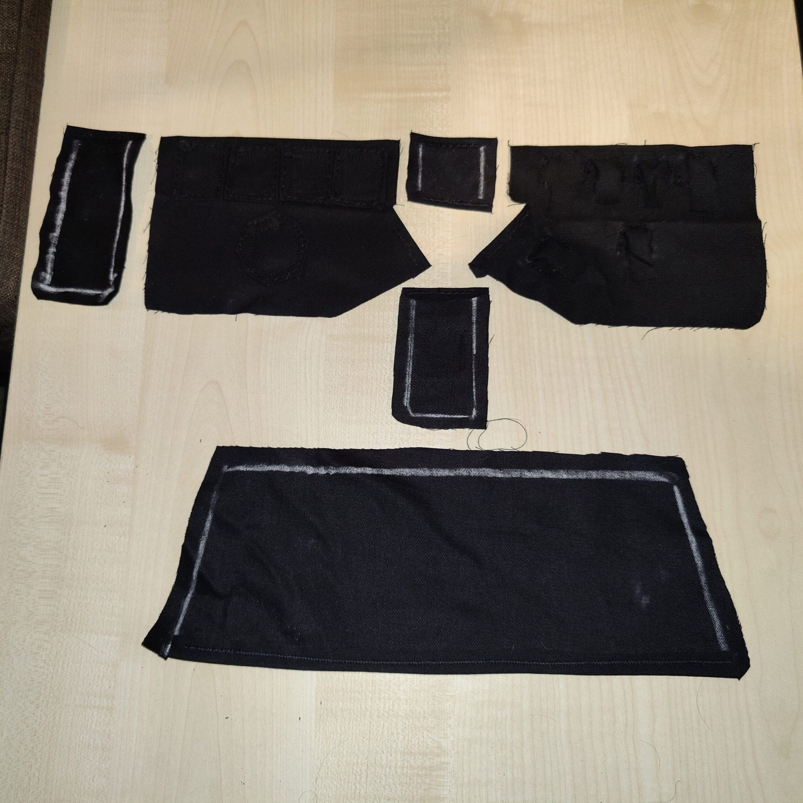
I transferred the templates to black cotton using chalk, which is a rather inaccurate method. I later got some wax pencils which worked a lot better.
With external edges hemmed
The first version was a little too tight to put on and take off, so a revised layer was made. I also decided to go with a single “bar” across the knuckles, with dividers sewn on top, instead of the individual stone pads I had originally used. This saved on complexity, and also supported the edges better which were a little wider than the finished glove layer.
Top sideUnder (palm) side
To the underside (where the palm will be) I added six miniature “pockets” for the tactile switches, each approximately 12x12x6mm in size.
With the glove inserted
I had actually made this prior to fabricating the circuit, so once I had a finalised size for the circuit board the last thing to do prior to assembly was to sew on a “sleeve” into which the circuit board would be secured.
With PCB sleeve
Simply a piece of fabric slightly larger than the board, with a notch sewn halfway across the top. Three of the LEDs would feed through either side, and the notch would prevent the board itself sliding through. Once inserted, I planned to sew a second notch in the bottom edge to hold the circuit board in place.