With the Printed Circuit Board (PCB) designed, the next job was getting it manufactured. Lacking the tools to do so myself, and having no experience ordering a PCB, this was a daunting prospect. Less daunting was sourcing the components for the circuit itself, with electronics components suppliers readily available online. I went with Bitsbox, a UK supplier whom over two orders were very quick to dispatch and deliver the components.
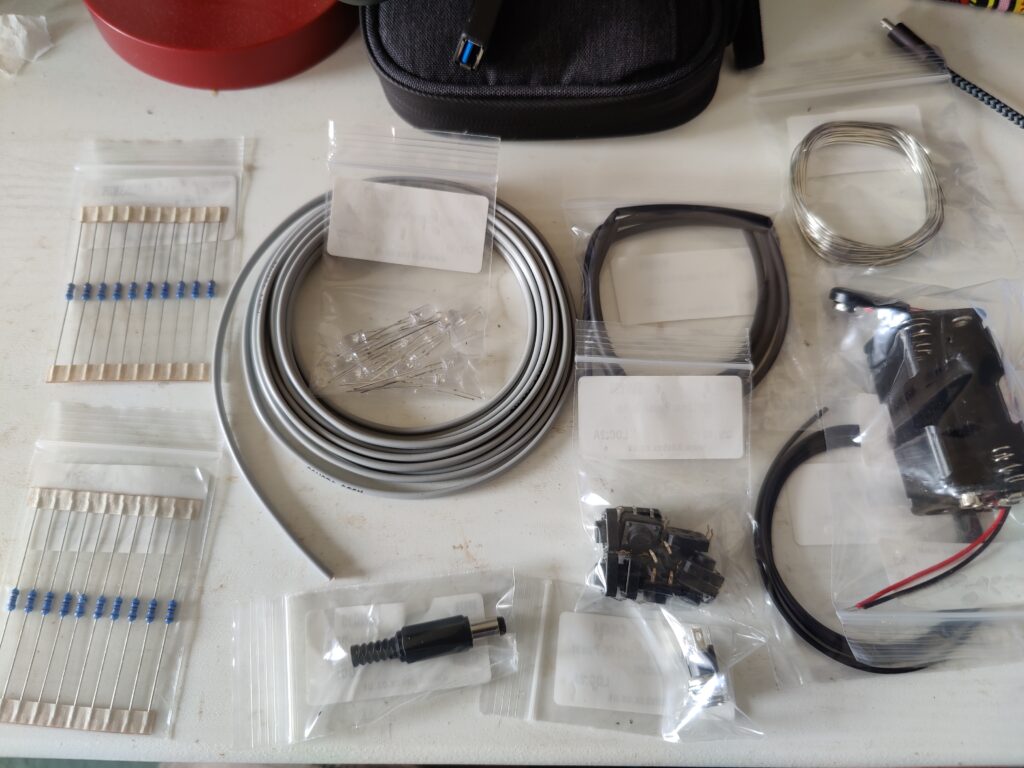
The components ordered include:
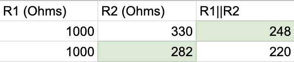
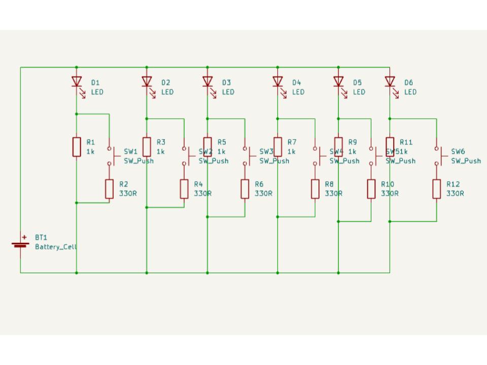
- 10x 1K resistors
- 10x 330R resistors
- 10x 5mm Ultra-bright white LEDs
- 10x 12mm tactile push switches
- 2.1mm DC power socket
- 2.1mm DC power plug
- 1x 4xAA battery holder
- 1x 9V battery clip (connects to the battery holder)
- 3m speaker wire (3m additional in second order)
- Heat-shrink sleaving
- Solder
The speaker wire is essentially a pair of wires bound together, which would make managing the cabling easier. The particular wire I ordered was grey with a black stripe down one side, which made it easier to keep track of the circuit polarity (as LEDs, being diodes, only work in one direction).
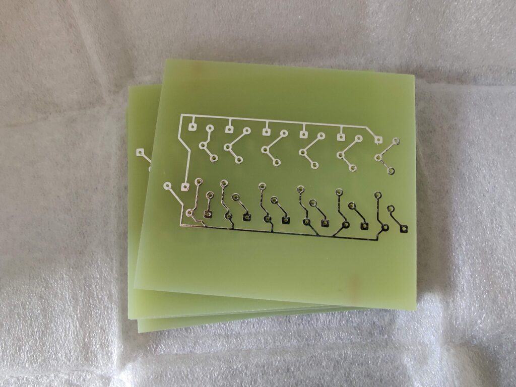
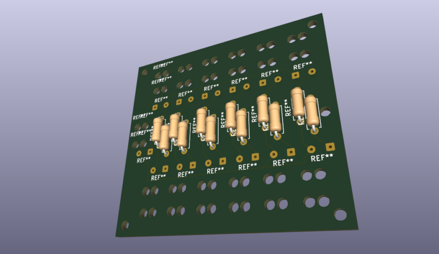
Trying to find a PCB manufacturer was difficult, as I am a hobbyist rather than someone looking to manufacture large batches of a given PCB. I initially tried to contact a few UK-based manufacturers, but with very limited success (as they seemed more set up for business-to-business interaction rather than making a small batch of custom boards). Looking to hobbyist websites it seemed that going to a Chinese manufacturer was the most cost-effective and easiest way to go, so I tried PCBWay. The interface seemed straight-forward enough to use and the pricing wasn’t astronomical, the only downside was I couldn’t get the extra holes drilled and the minimum batch order was 5. This wasn’t too much of an issue as having spares would be handy, and the PCB layout could work for any generic lighting circuit up to 6 LEDs so could be useful in future projects. Including delivery, I went from order to having the PCBs in hand in just over a week:
Lacking the ability (and skill) to drill the extra holes myself (the manufacturer did drill the holes in the circuit contacts), I figured the best thing to do was to solder the whole circuit together when the gauntlet’s underlayer was ready to have it installed, since once it was secured in place any stresses on the wires should be minimised. The first task however was to solder the resistors into place, which I could do right away.
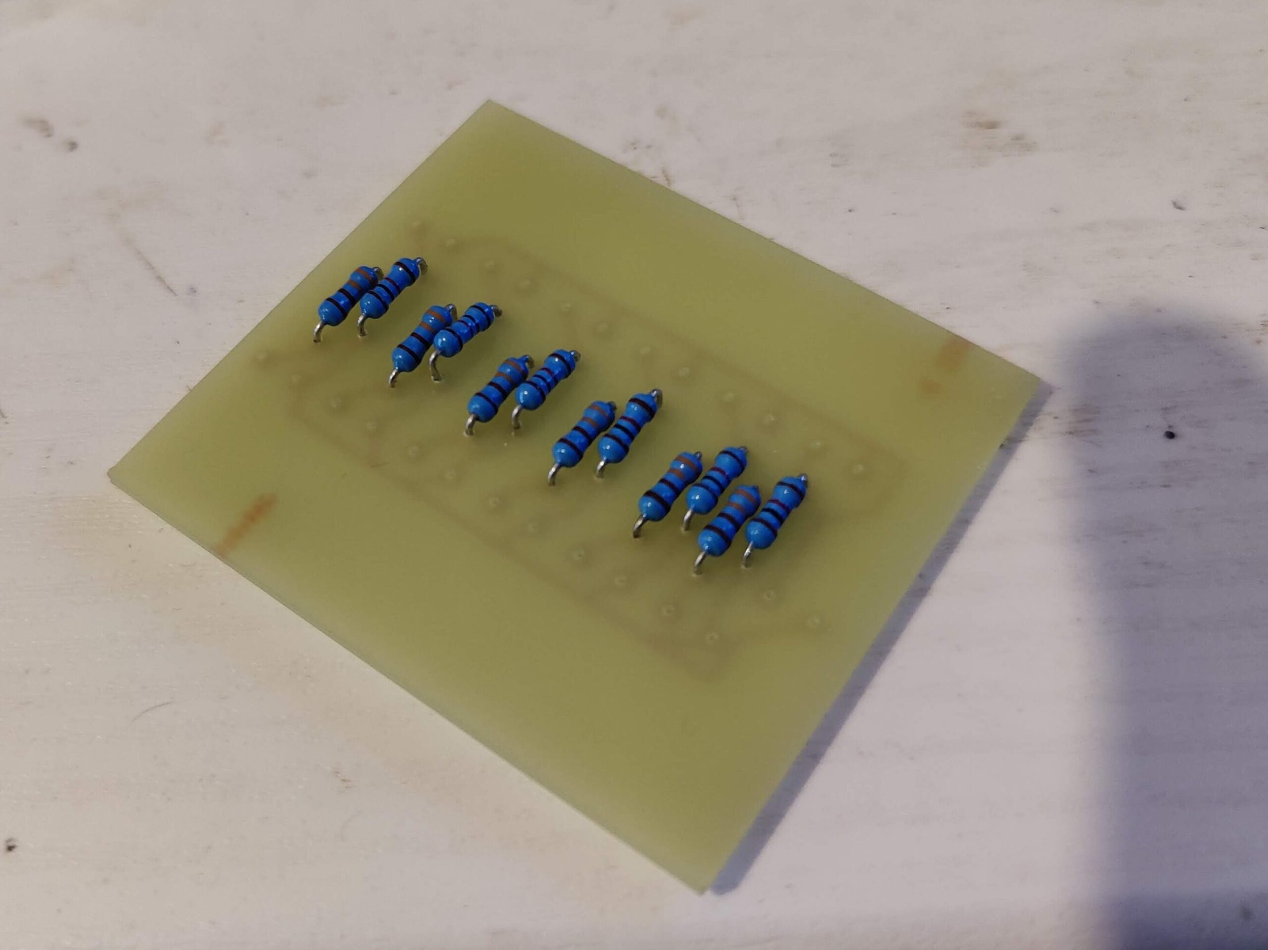
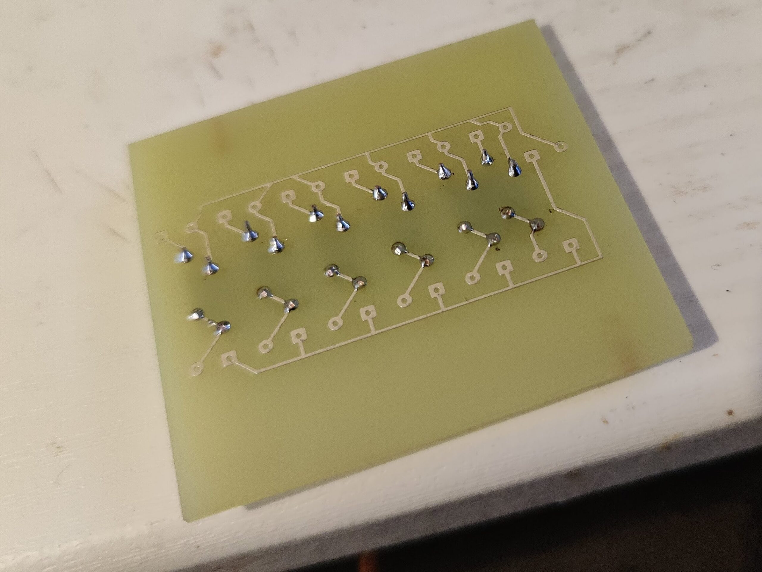
I used to be pretty good at soldering back in secondary school, I think I’ve gone a bit rusty. Once soldered, I tested the circuit with a multimeter to make sure the solder joints were conducting current adequately.
The rest of the circuit involved measuring the approximate length of each wire needed, based on the planned route from the board to the component’s location on the gauntlet (either on the back of the hand or on the palm), adding a generous extra length (at least 10%) for losses when soldering, as well as a bit of room for placing the wires. (Better to have a bit too much cable than not enough).
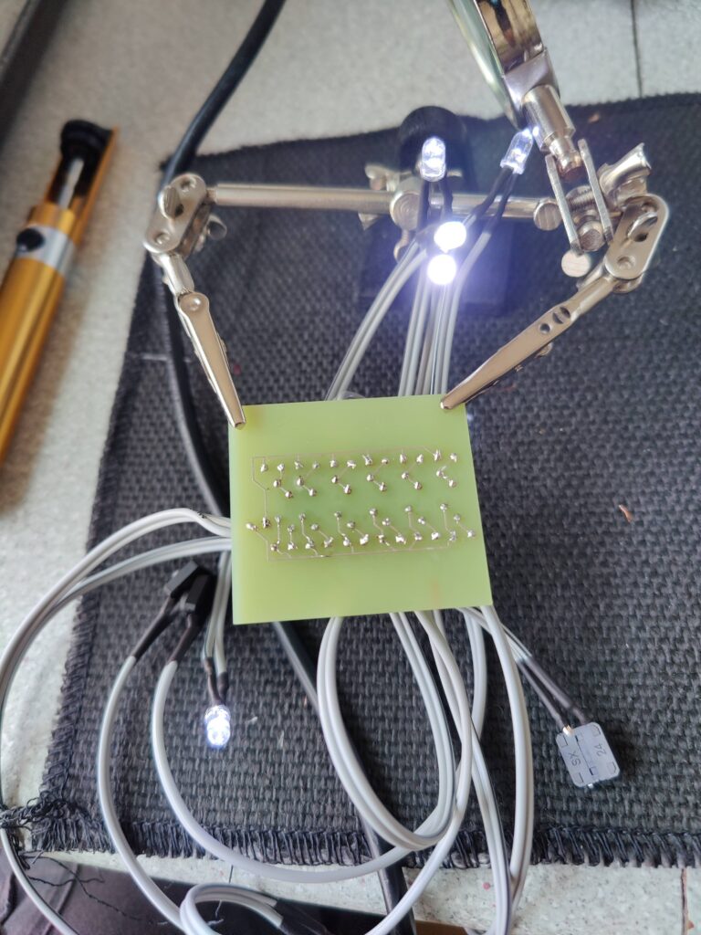
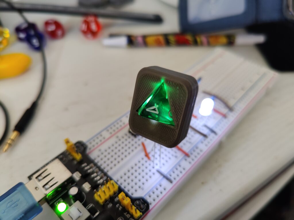
The LEDs were relatively easy to solder, with long legs they’re designed to be soldered to wires or directly into boards. The main concern was ensuring I soldered the correct wire to the correct leg (I wanted to keep the wire with the black stripe as the positive/anode).
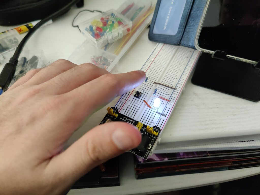
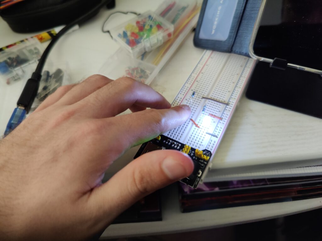
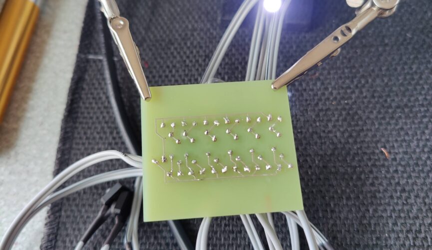
The tactile switches were a pain, since they are very much designed to be soldered directly onto a board, and not to wires. The tabs are very small and getting the wire to mesh with them enough to take solder was fiddly to say the least. The solder joints are far from the best I’ve ever done. But a few hours of work (with testing the circuit after each pair of LED/switch were added) thankfully yielded a successful result:
Now with the lighting circuit made (and the gauntlet’s underlayer, which was ready by this point but I will document in a later post) it was finally time to bring it together…
![\[ V = IR\]](https://cosplay.danielsmedley.com/wp-content/ql-cache/quicklatex.com-2ad3b298d8156a7868110630d6443d9d_l3.png "Rendered by QuickLaTeX.com")
![\[ \frac{1}{R_{T}} = \frac{1}{R_{1}} + \frac{1}{R_{2}} + \dots + \frac{1}{R_{n}}\]](https://cosplay.danielsmedley.com/wp-content/ql-cache/quicklatex.com-372d01ab73b5e25e5b2d8761730202b2_l3.png "Rendered by QuickLaTeX.com")