
When conceiving the idea for what I’m loosely calling the “Infinite dGauntlet” a number of ideas came to mind. The “ideal” functionality and look that I would aim for, and the levels below that I could achieve if resources/time became too much of a constraint. The ideal in this case would be individual illuminations for each dice, and the ability to selectively brighten any/all of the dice by the action of closing the fist. Failing that, illuminating the dice would be a more achievable goal.
5mm Ultra-bright White LEDs seemed an obvious choice, they would likely be small enough to fit inside a 3D-printed mount for each dice yet powerful enough to provide sufficient illumination.
For control, a few options came to mind. Reed switches combined with magnets sewed into the fingertips might have worked, but with a number of the switches in close proximity it may have been difficult to selectively activate them. I eventually decided the simplest option would be some variety of tactile push-to-make switches, generally flatter I figured they would quite easily be sewn into the gauntlet.
So the question arose: How to use a push-to-make switch to make an LED brighter when pushed? A brief bit of research on LED brightness (googling and answer on StackExchange) unearthed the fact that LED brightness is roughly proportional to the current flowing through it. Remembering Ohm’s Law from secondary school:
![\[ V = IR\]](https://cosplay.danielsmedley.com/wp-content/ql-cache/quicklatex.com-2ad3b298d8156a7868110630d6443d9d_l3.png "Rendered by QuickLaTeX.com")
Where V is Voltage, I is current and R is resistance
The plan for the circuit is to run on 4xAA batteries, so the voltage across the LED will be fairly constant. This means Current will be inversely proportional to resistance.
The second piece of the solution comes from how components of a given resistance (namely resistors) combine. In series, resistances combine by simple addition, but in parallel it is their inverses (or conductances) that add together:
![\[ \frac{1}{R_{T}} = \frac{1}{R_{1}} + \frac{1}{R_{2}} + \dots + \frac{1}{R_{n}}\]](https://cosplay.danielsmedley.com/wp-content/ql-cache/quicklatex.com-372d01ab73b5e25e5b2d8761730202b2_l3.png "Rendered by QuickLaTeX.com")
Essentially this means that two resistors in parallel have a total resistance that is less than either resistor individually. This means I could place a push-to-make switch alongside a second resistor, both connected in parallel with the first. Then when the button is pushed, the resistance of the entire segment is reduced, the current increases and the LED shines more brightly.
Given my knowledge from secondary school electronics, I recall we would always use a 220 Ohm resistor with LEDs, so figured that was a reasonable lowest resistance/highest current for the “active” higher illumination state. I wanted there to be a noticeable difference between the two states, so went with a 1,000 Ohm resistor for the inactive state. Knowing the desired total resistance and value of resistor R1 figuring out a suitable R2 was relatively straightforward:
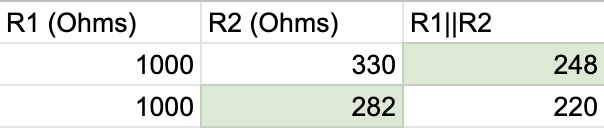
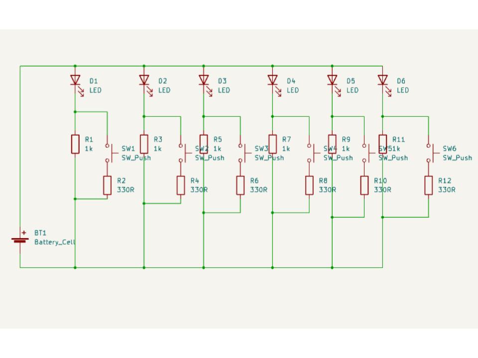
The exact R2 I would need was 282 Ohms, but 330 Ohms (a more standard fixed resistor value) got me to 248 Ohms, which was close enough. So the basic unit of the circuit would involve an LED and 1 Kilo-ohm resistor, always connected, with a second 330 Ohm resistor and switch in parallel with the 1 Kilo-ohm resistor. Multiply that by six for each light, and the circuit diagram looks something like:
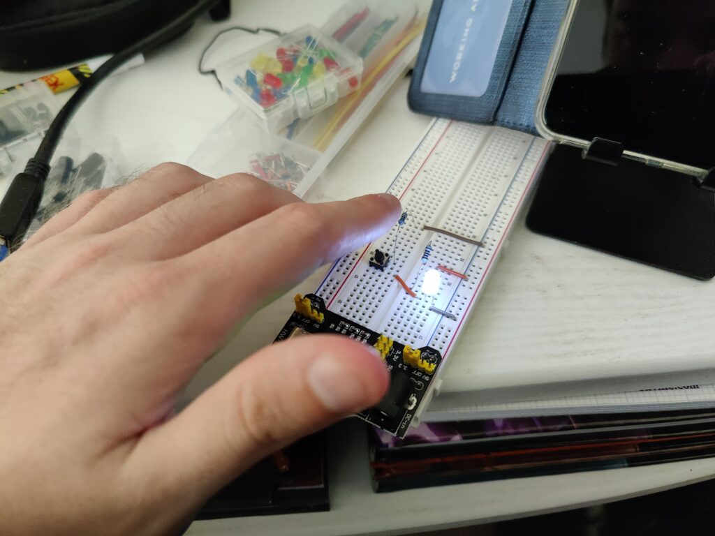
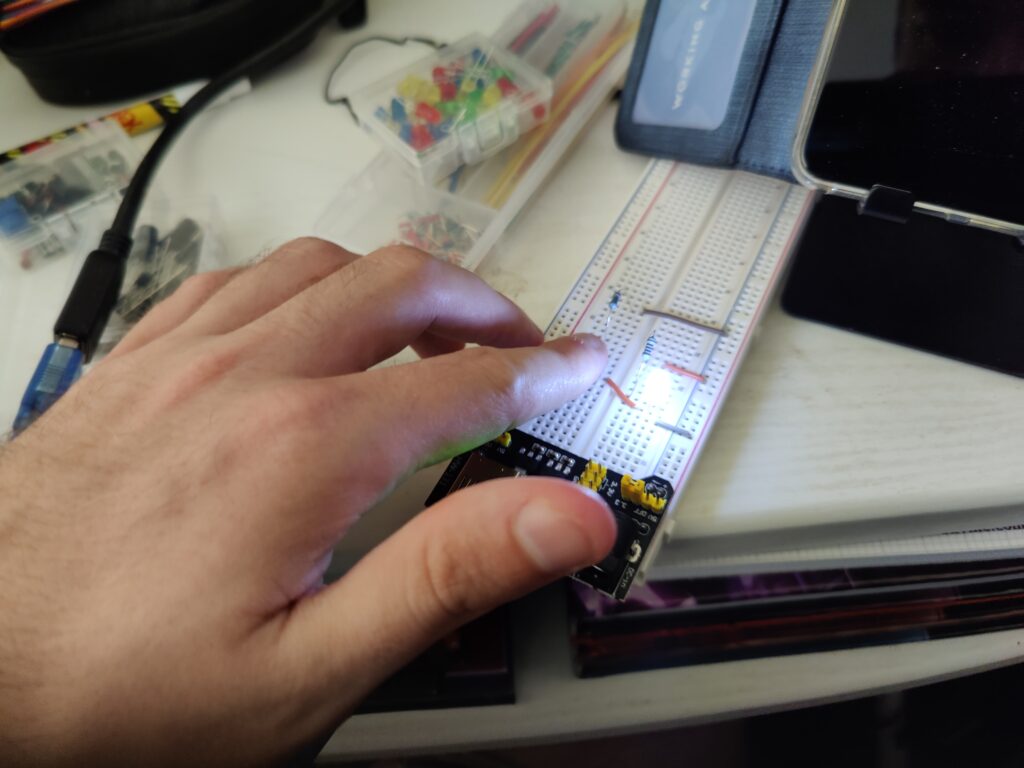
All good in theory, but before I want to the trouble (and expense) of turning this into a circuit board I wanted to be sure it would actually work. It was finally time for me to get myself a breadboard. I found this kit on Amazon for a reasonable price and quick delivery, and before long I had wired up a prototype.
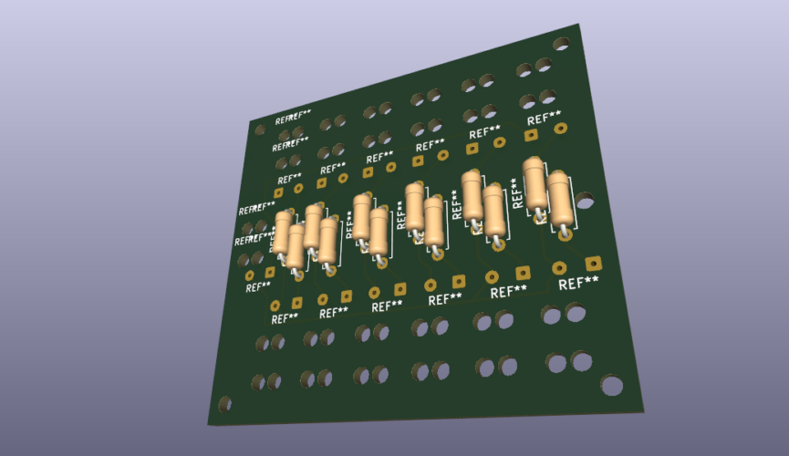
With the circuit figured out, the next task was transferring it to a Printed Circuit Board layout. Once again my experience from school was limited, the software we used (which I cannot remember the name of) was fairly basic. KiCad seemed to be the best open source software for designing PCB layouts, though it has something of a learning curve. (Multilayer PCBs, solder masks and a whole catalogue of component footprints.) However I managed to figure out enough to lay out the circuit I needed. The main challenge was figuring out a design that would be small enough to fit into the gauntlet, but not so small as to be too difficult to solder together. With six LEDs and six tactile switches, as well as a power input, there would be 13 pairs of wires to attach which seemed like it would be too crowded, but this is what I eventually came up with:

The holes were intended as mounting points for the board as a whole, as well as a means by which to secure the wires. In secondary school electronics we would thread a wire through larger drill holes in the PCB before soldering, as doing so meant any forces on the cable wouldn’t be directed into the solder joint, which can be brittle and break easily. I wasn’t sure whether I could find a manufacturer who could drill the holes as specified, or indeed if holes so close together were even feasible for the board material. However if it wasn’t possible I had planned to secure the wires to the gauntlet itself so, once installed, stresses on the solder joints should be minimal.
Now all that was left to do was order in the components and try to get the board manufactured.