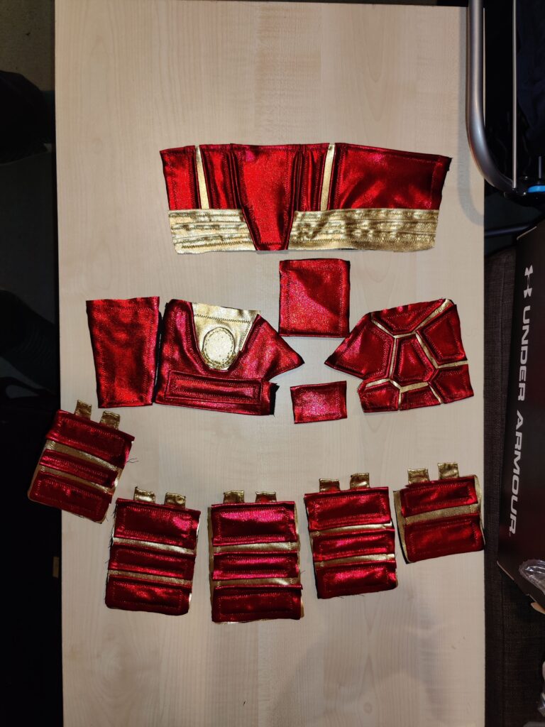
With the gauntlets made, the remainder of the costume was next. My original plan was to do a full-body costume, with trousers and boot-covers. However with looming time constraints I had to prioritise, which meant focusing on the upper body first. The upper body would be broken down into three main pieces: The sleeves, to be attached to a plain black sweater; the vest to be worn over the sleeves (and attached if time allowed) and the collar to be worn over the vest.
The Sleeves
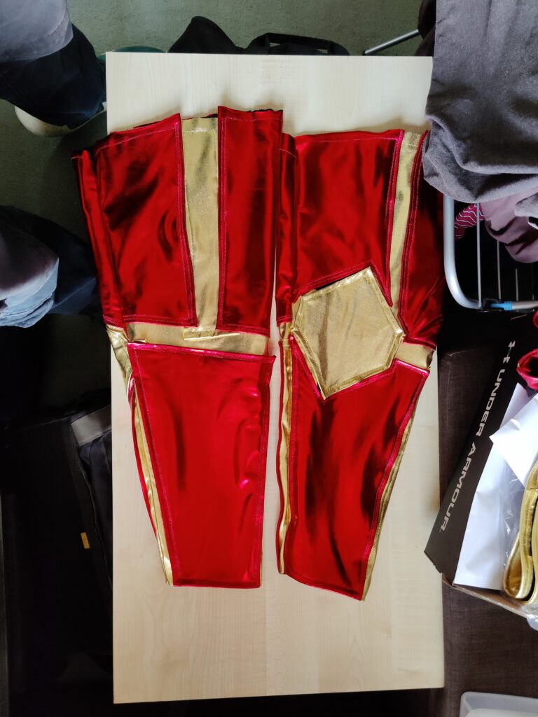
Measuring the black sweater as a template, I marked the rough location of my elbows while wearing the sweatshirt in order to estimate where on the pattern to place the elbow pad, and to work the design out around there. The design would involve sections of metallic red spandex as “plates” of armour separated by strips of gold spandex sewn underneath.
Black cotton with gold underlayerRed sections appliedBoth sleeves sewn into tubes
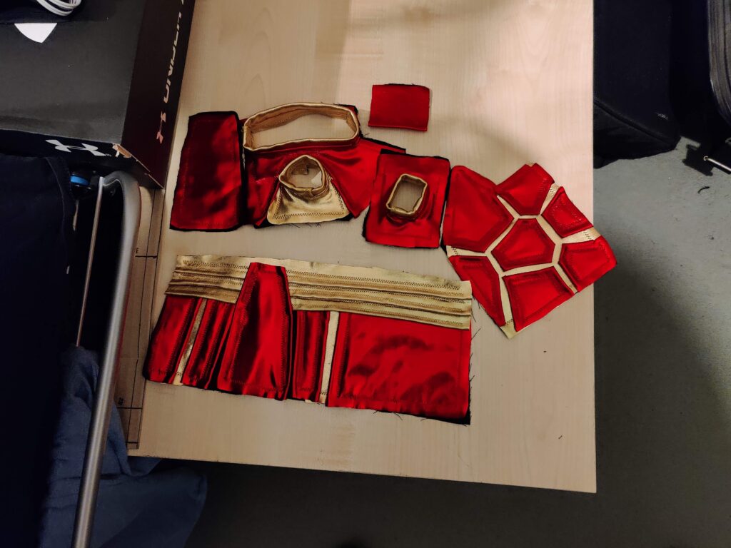
The Vest
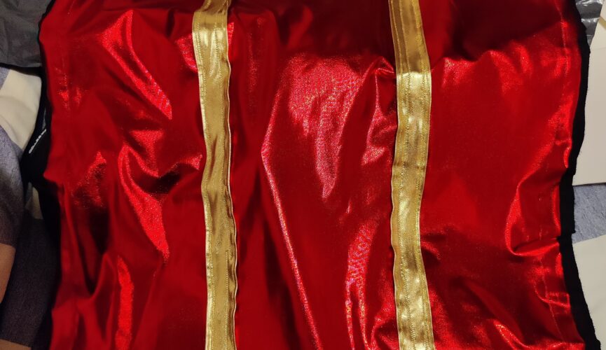
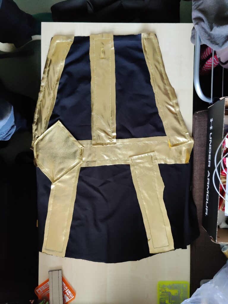
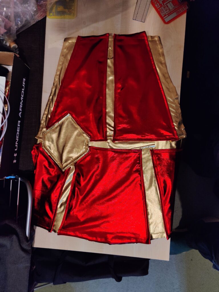
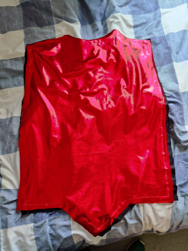
With limited knowledge of sewing patterns, I used the sweater again as a guide, combined with rough measurements of myself to get the sizing right. Knowing the limitations of my experience, I added some margin to these measurements, but in the end the vest still ended up very tight to wear. It involved two pieces, a front and back, with the red spandex as an underlayer and strips of gold spandex for a bottom border and vertical “seams” across the front.
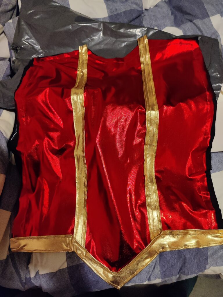
Base layer (slightly misaligned)With gold features
Even with the walking foot sewing machine head (which was such a worthwhile purchase when dealing with the spandex) over longer seams and a greater number of thread breaks the alignment between the two base layers drifted noticeably, but not beyond the excess material I had left around the template. The rear section was similar to the first, lacking the V-shaped extension at the bottom and only featuring the lower horizontal border of gold.
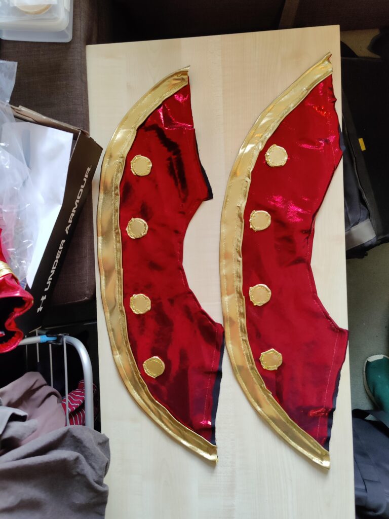
The Collar
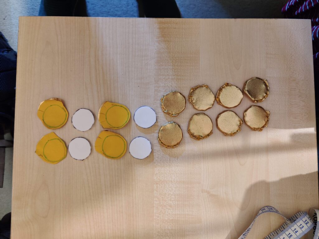
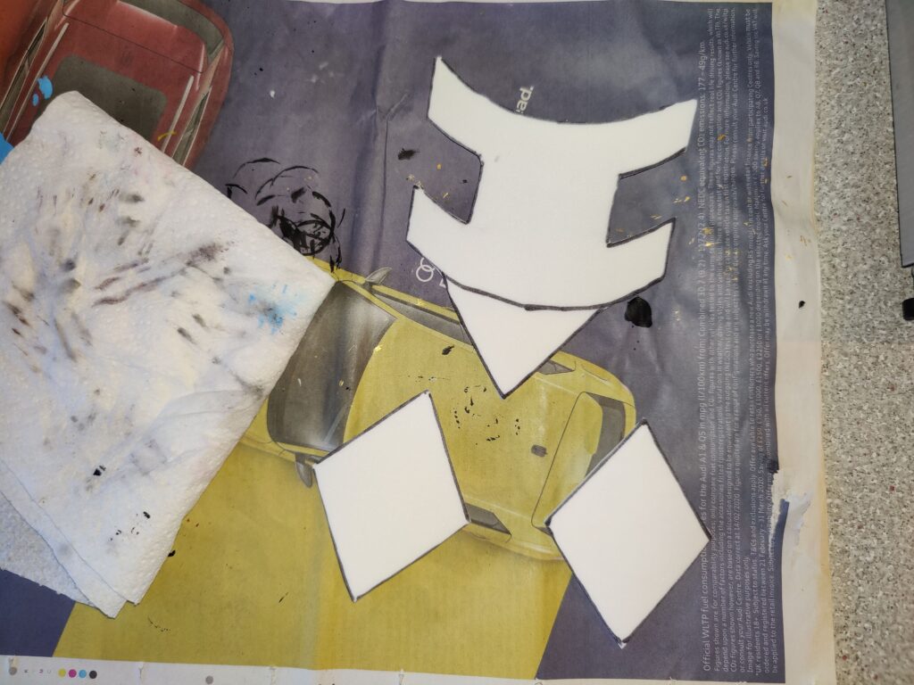
I created the collar using a darker metallic red fabric I had managed to find online. To create the gold “pips” I cut pieces of 3mm foam into circles and sewed a layer of gold spandex around them.
Gold collar pips being created
The collar was made from two pieces, with an outer border of gold spandex and eight coins/pips sewed on.
Darker metallic red base layerWith gold features added
The Necklace
An additional component was the Dungeon Master’s pendant or necklace. Lacking the time to design/print a more 3D version, I resorted to trusty old 3mm foam and hot glue to create a makeshift version.
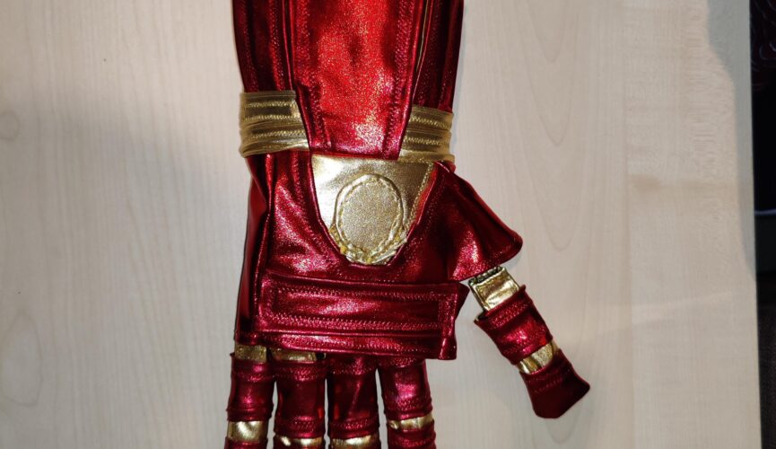
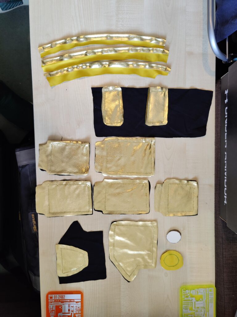
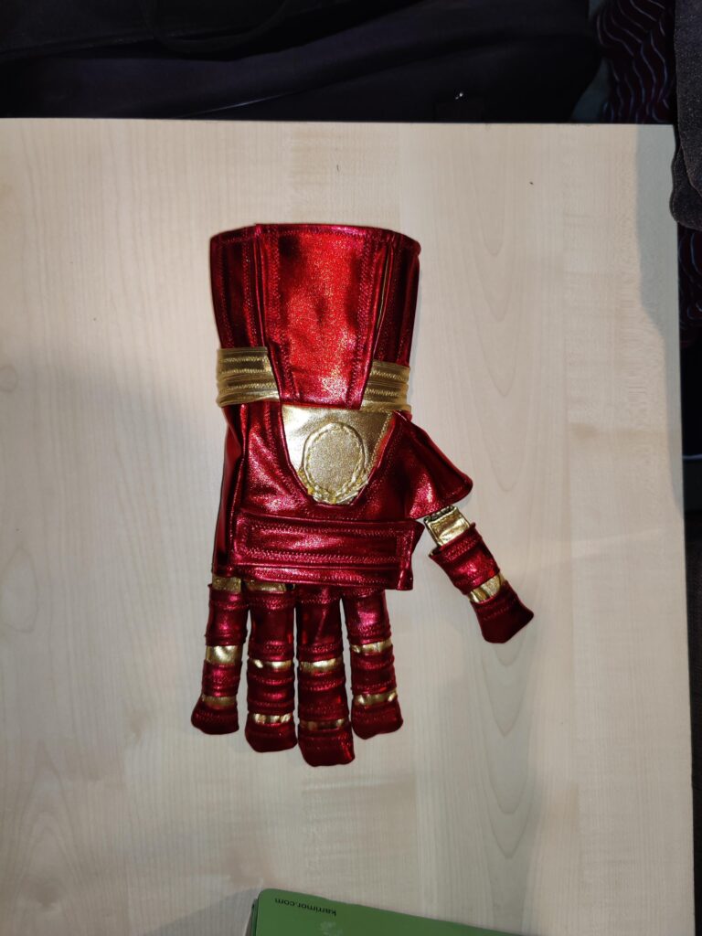
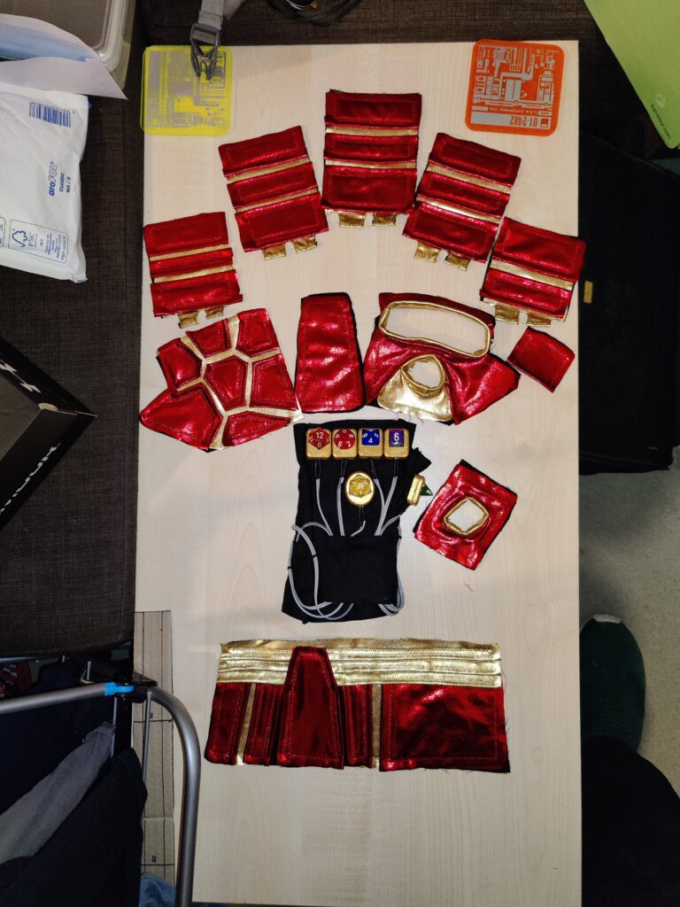
Creating the corresponding right-hand gauntlet for DMos was, predictably, a much easier and quicker process. With no circuit or inner layer and the templates for the outer design already crafted, the only real task was modifying the design to remove the dice mounts. This would be achieved by replacing the knuckle-mounted dice with a simple “bar” of metallic red spandex, and replacing the larger oval d20 mount on the back of the hand with a flat oval piece of gold spandex.
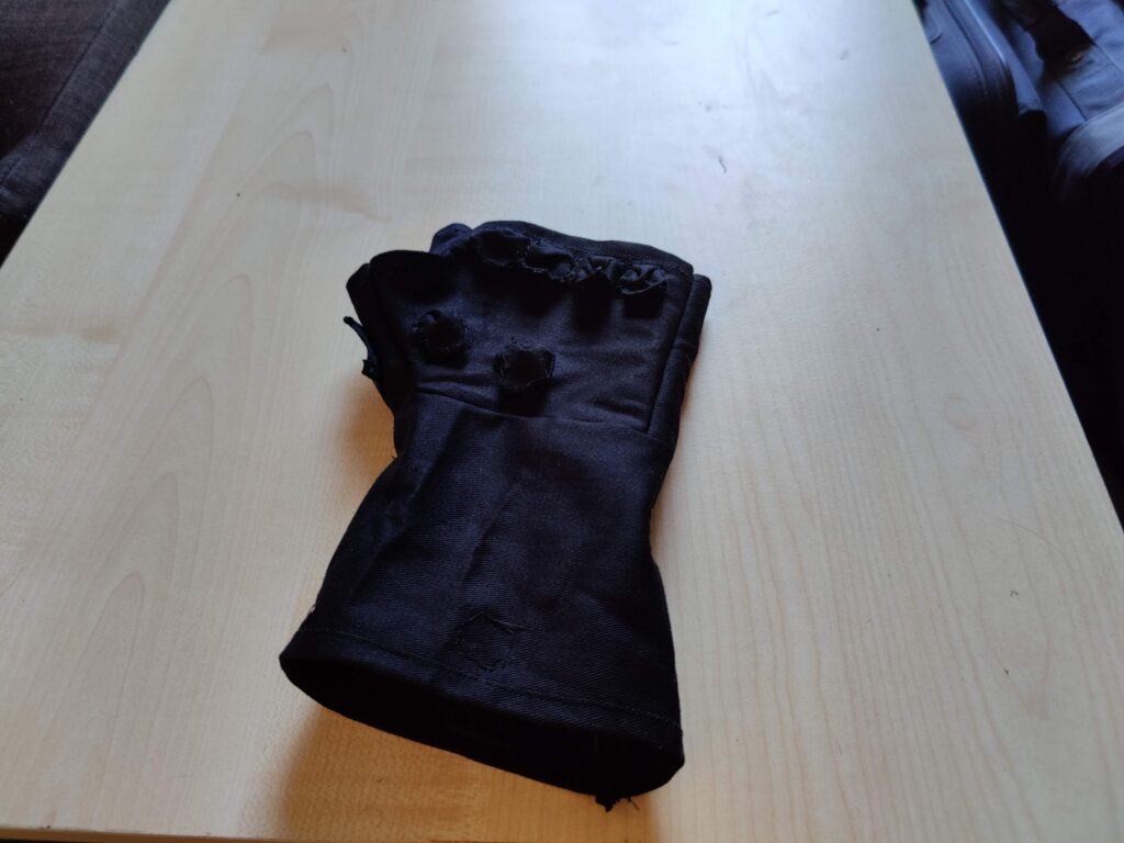
Base black cotton layer with first gold spandex layer
To help give the gold oval its shape, I used 3mm foam to cut an insert around which the material would be sewed. As with the other gauntlet, a base of black cotton was used, with an initial layer of gold spandex.
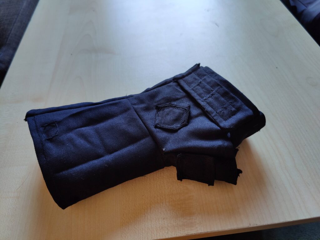
Right gauntlet pieces
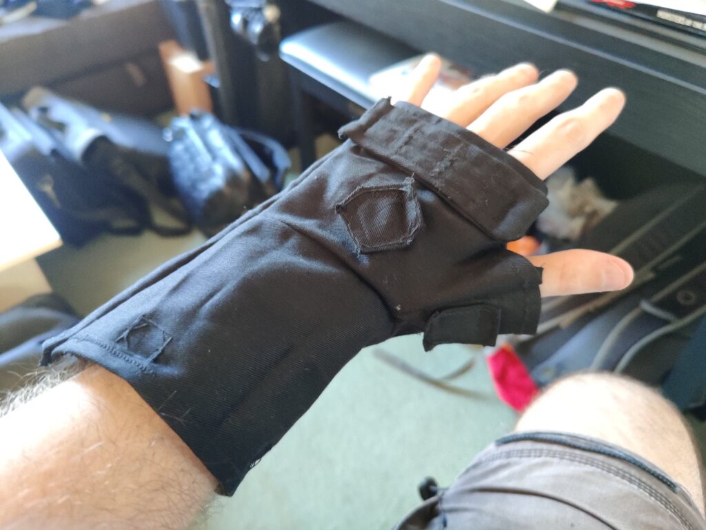
As with the other gauntlet, the red and gold spandex had to be layered to achieve the desired design. Unlike the other gauntlet the outer layer was attached directly to the inner glove.
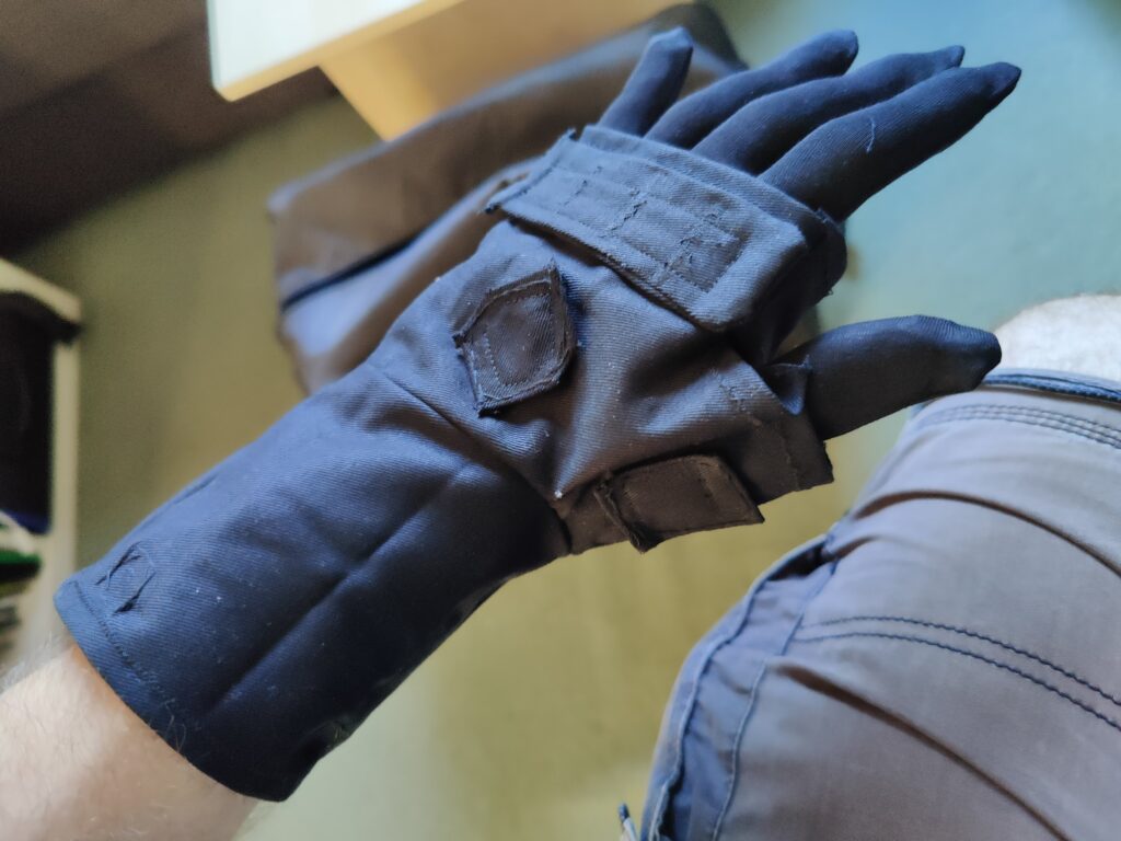
Right gauntlet assembled prior to attaching to glove
With the pieces of the gauntlet assembled, they just needed attaching to the inner glove in the same manner as before. The gauntlets were by far the more intricate aspects of the overall cosplay, but the remainder of the costume would be considerably larger and, with a temperamental thread all to happy to snap in the sewing machine, considerably more annoying to put together.
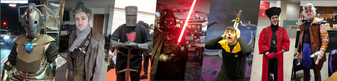
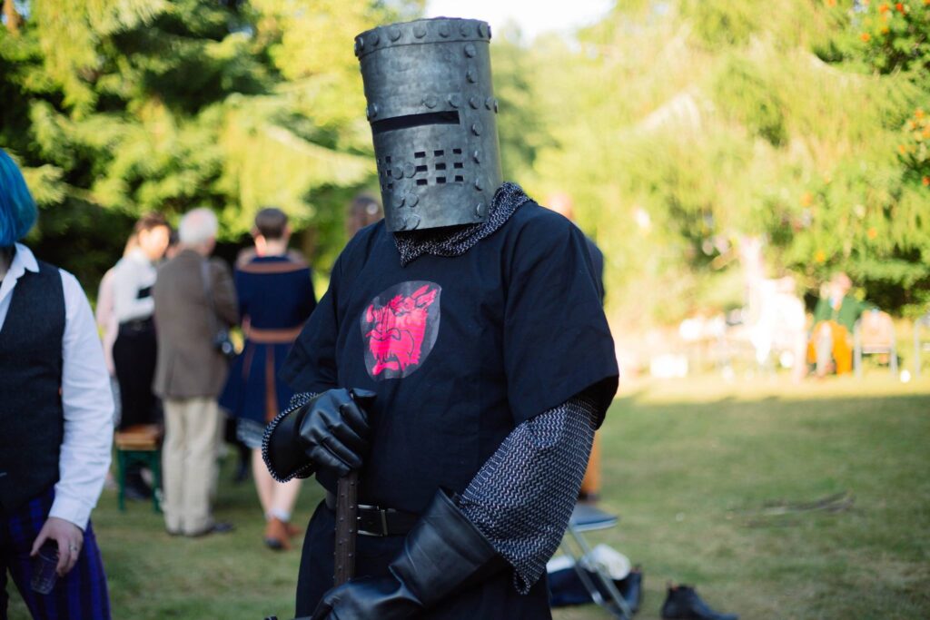
In the first of what I hope to be a number of retrospectives looking back at a few of my earlier cosplays, we roll the clock back to early 2018. Having had initial success with my Cyberman and War Doctor Cosplays at October MCM (2016 and 2017 respectively) this was the first time I would be attending the May comic con in costume. I would learn that designing costumes for specific conventions would require some consideration of the time of year, but this costume may have been the one to teach me that lesson.
With a couple of solid Dr Who costumes under my belt I wanted to branch out a little. Monty Python had always been a favourite in my household growing up, and the Holy Grail seemed a good medieval fantasy aesthetic with which to break out of my Science Fiction cosplay roots.
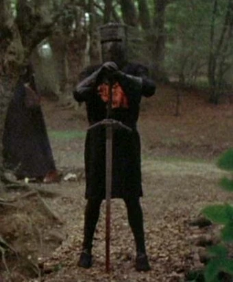
As with all my cosplays I intended to make at least one component from scratch, and evidently the helmet would be the prime candidate, and thus the focus of my efforts. The rest, including a LARP-safe sword, I would seek to purchase, along with inkjet-printable iron-on transfer paper for the symbol on the tunic. I sourced a close-up screenshot of the helmet to use as a reference.
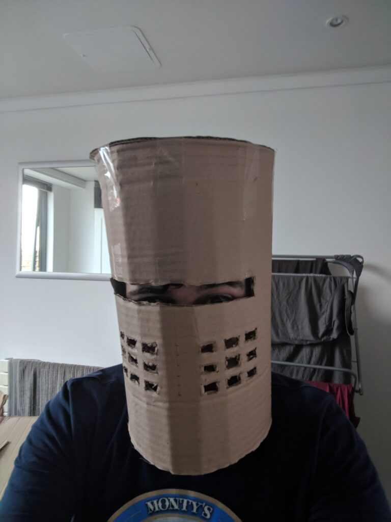
The plan was to use two layers for the helmet: An inner layer of 3mm foam for comfort, and an outer layer of Cosplayflex thermoplastic for the outer layer. Between the two layers I would sandwich a layer of thin black fabric (sourced from a pair of tights) to obscure the inside of the helmet whilst maintaining some visibility. As I had not worked with Cosplayflex before, I considered this the new material/skill I would encounter for this project. The first step was, of course, the cardboard prototype, to check and confirm measurements and fit:
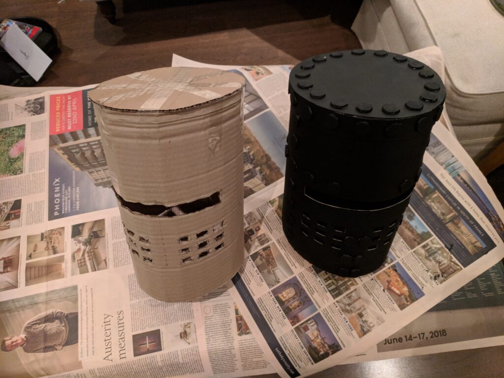
Cardboard Prototype
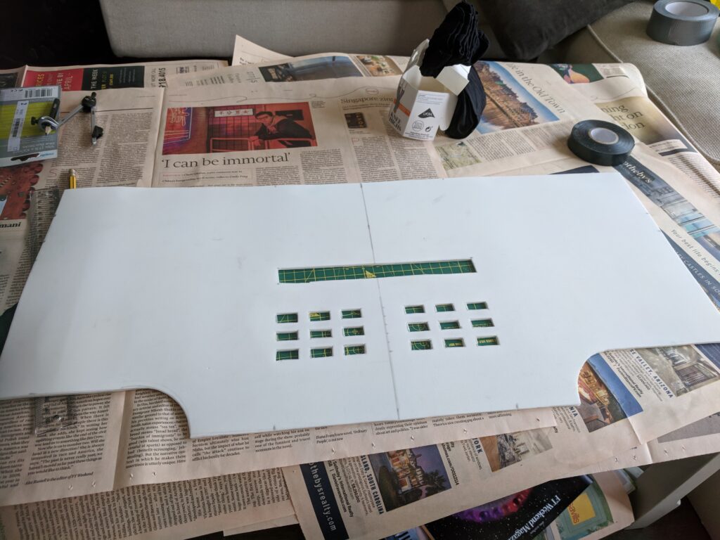
A few adjustments to line up the eye slit correctly were required, but overall the prototype was a success, so I felt confident moving on to the actual manufacture. First I focused on cutting the 3mm foam inner layer, along with a circular T-shaped piece, the goal of which was to go around the inside at approximately ear-level to hopefully secure the helmet at the correct height, as well as provide a joining surface for the seam at the back of the helmet.
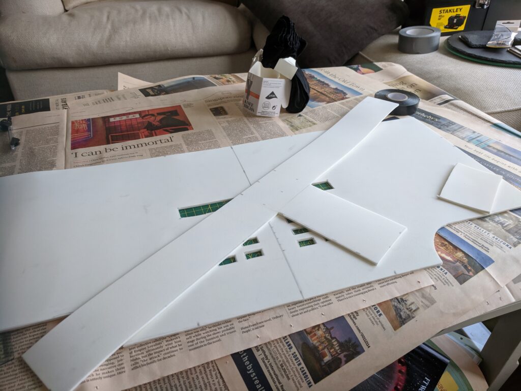
3mm foam layerT-shaped section for patching the seam
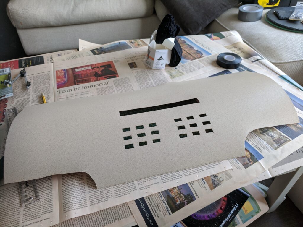
I had originally purchased a heat gun so that I could try and mould the Cosplayflex to the desired shape, but given it came as a roll already it seemed to fit a cylindrical design without the need for it.
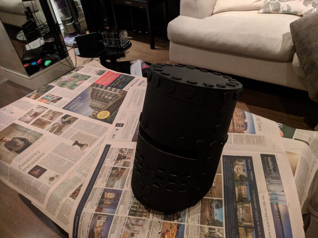
Outer Cosplayflex layer
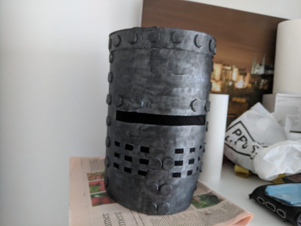
The Cosplayflex was surprisingly easy to work with, even using scissors and a craft knife to cut the pieces. I cut a circular piece for the helmet top from both 3mm foam and plastic, as well as a narrow rectangular piece of the plastic to patch over and reinforce the back seam. Then it was a matter of lots of hot glue, as well as the addition of the “rivets” which I simply cut from more 3mm foam. I also added a top ring of plastic.
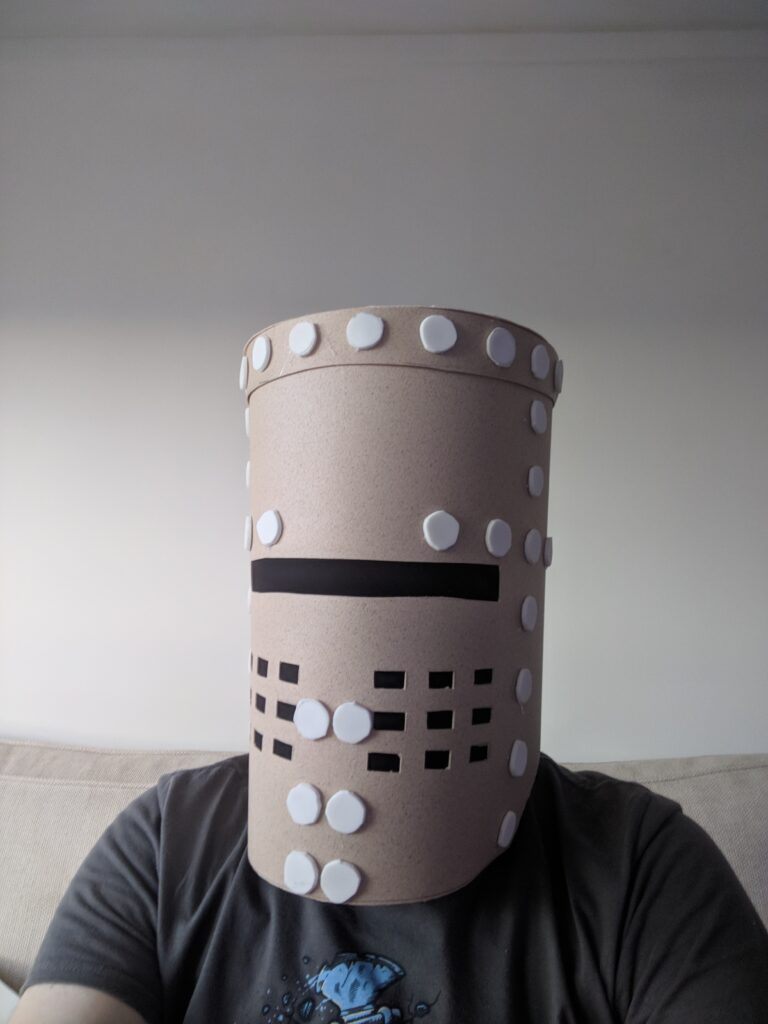
Final product prior to paintingFit test
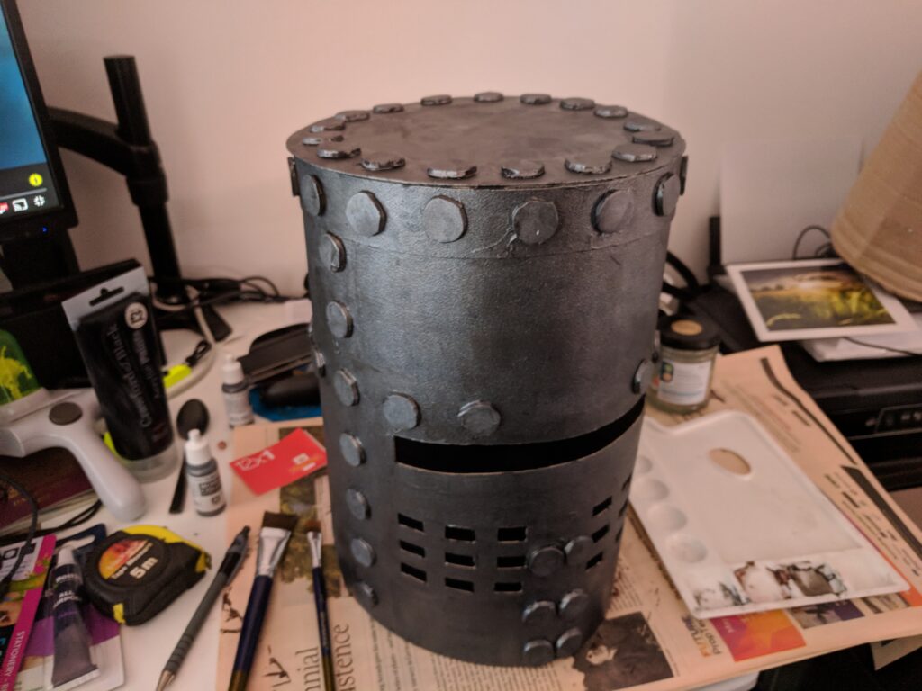
Painting the helmet involved a base layer of black, followed by a layer of “Natural Steel” metallic paint (two layers of each) followed by a black wash.
Black base coatAlongside prototypeSteel colour coatWith a black wash finish
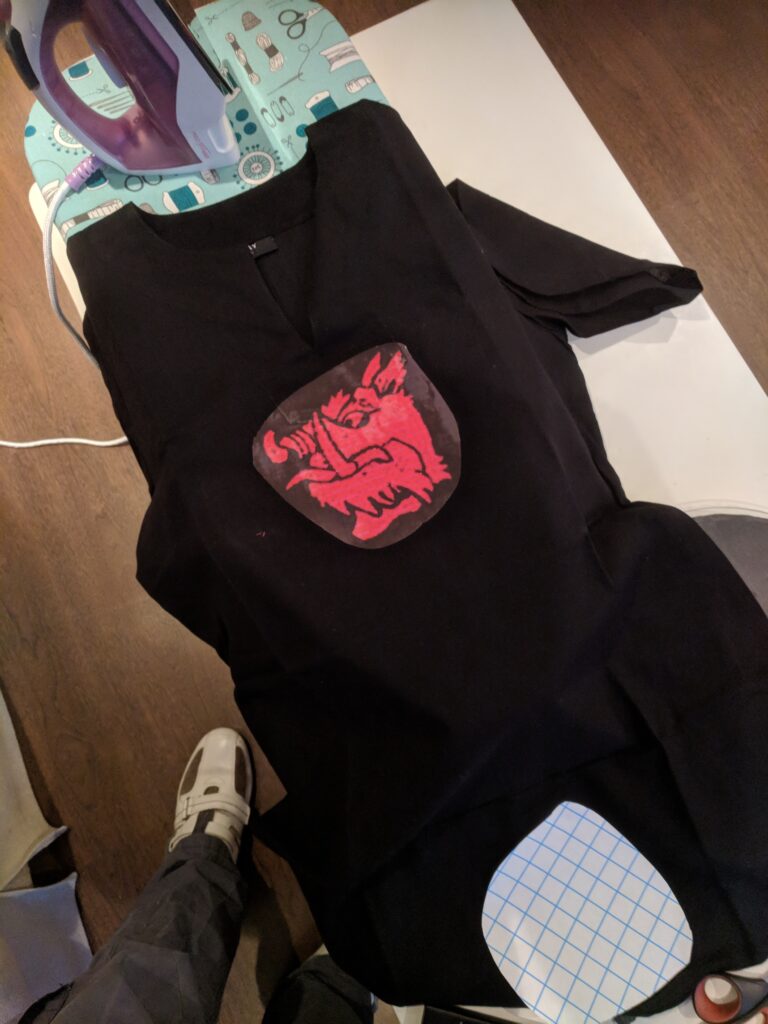
The only other piece of the costume that I had to create was the tunic, which was the combination of a black medieval costume tunic with an iron-on transfer (which unfortunately limited the size of the image I could apply to A4).
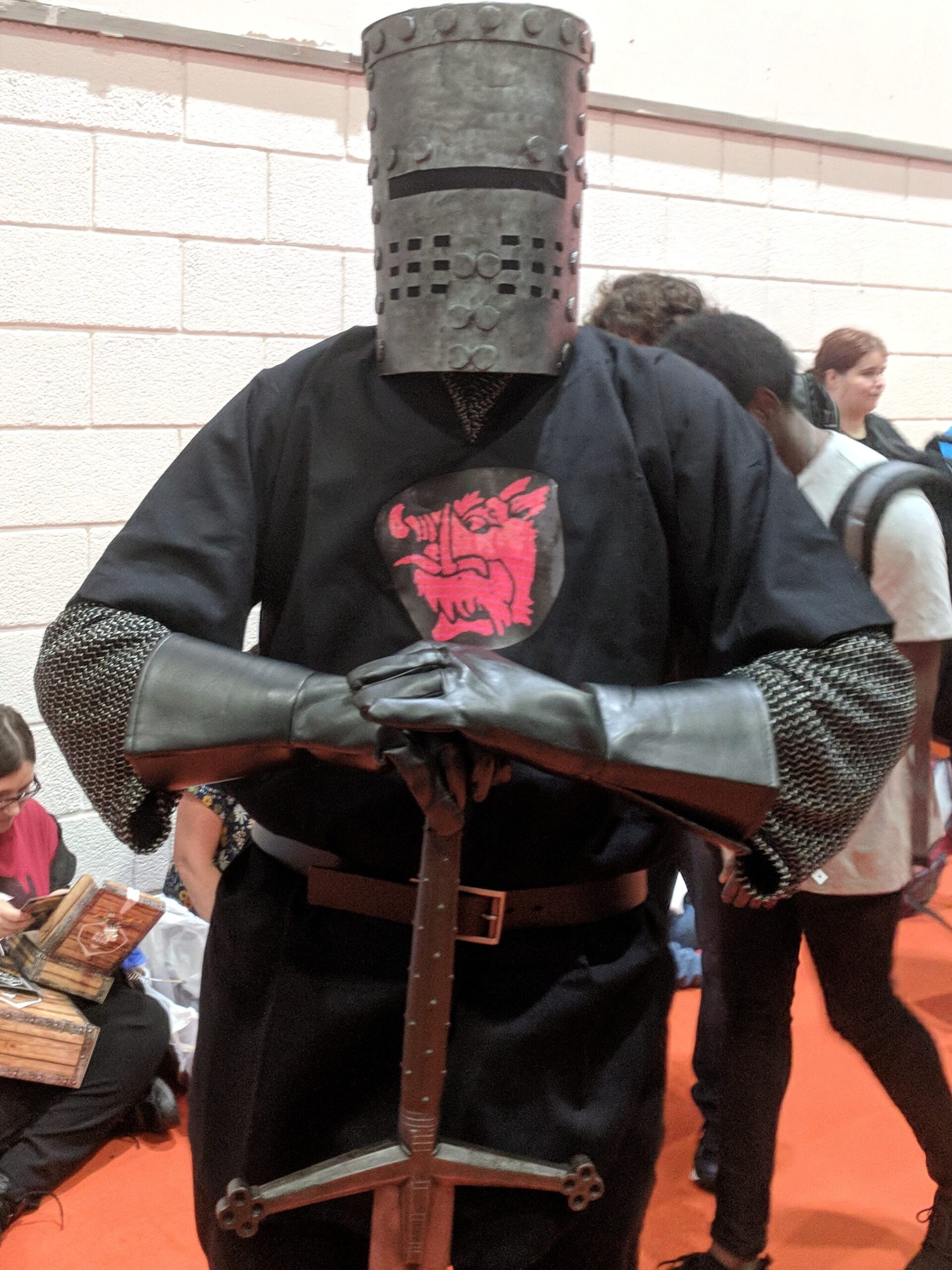
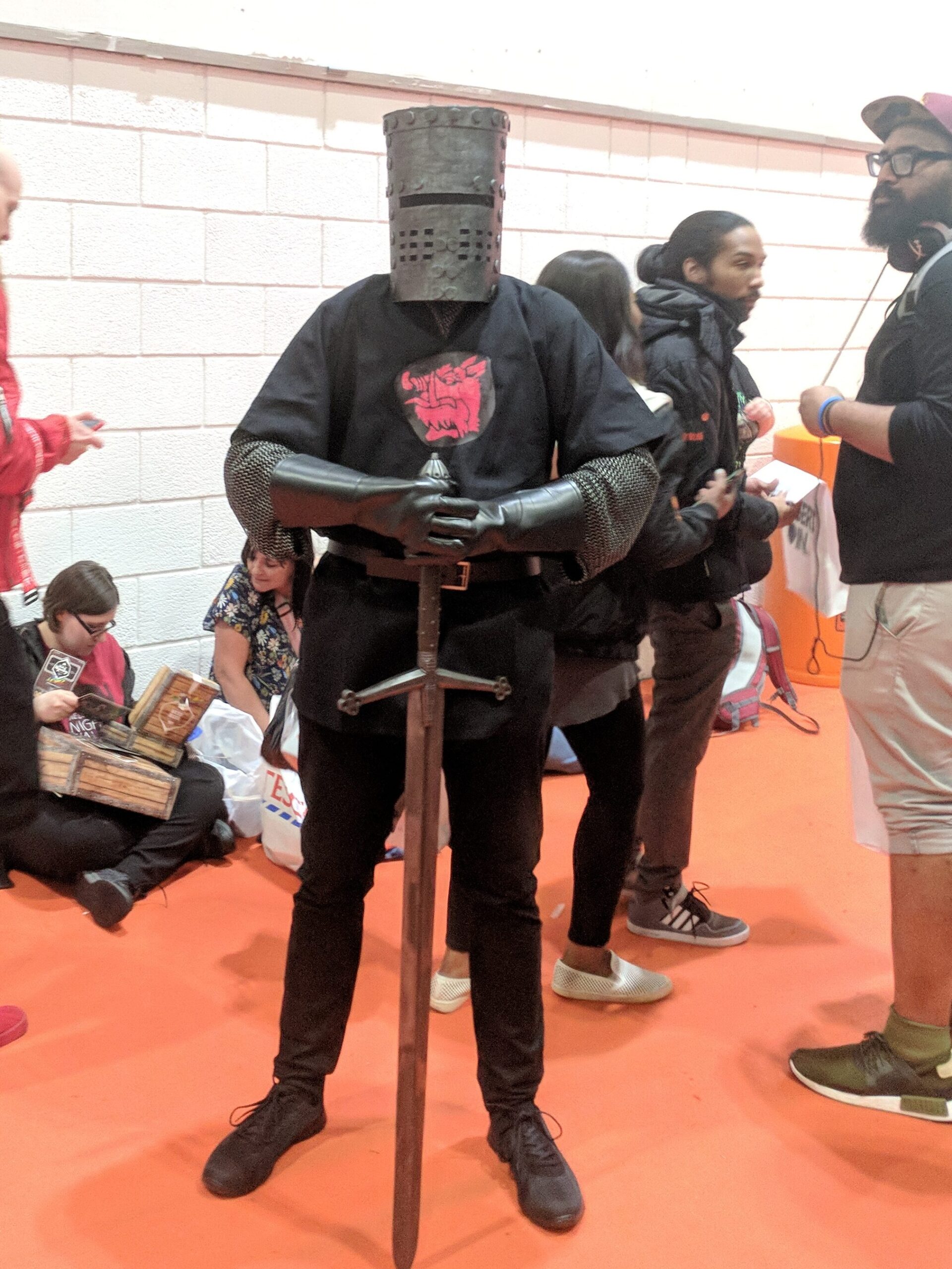
The remainder of the costume was purchased, including a costume chainmail shirt, faux-leather black gloves, and a LARP-safe sword as close to the Black Knight’s as I could find. The brown belt, black trousers and shoes I already had.
The costume was fun to wear, and got a fairly positive response at the convention. The visibility from the helmet was quite good, considering, however with the outer plastic layer it was heavy and did not take long to become uncomfortable to wear. If I were to remake this costume again, I would definitely use two layers of 3mm foam for a lighter and more comfortable helmet, even if it would sacrifice the rigidity the plastic provided. I would also try and hand-sew the tunic design, as it was a single colour and not too intricate to create, given time.
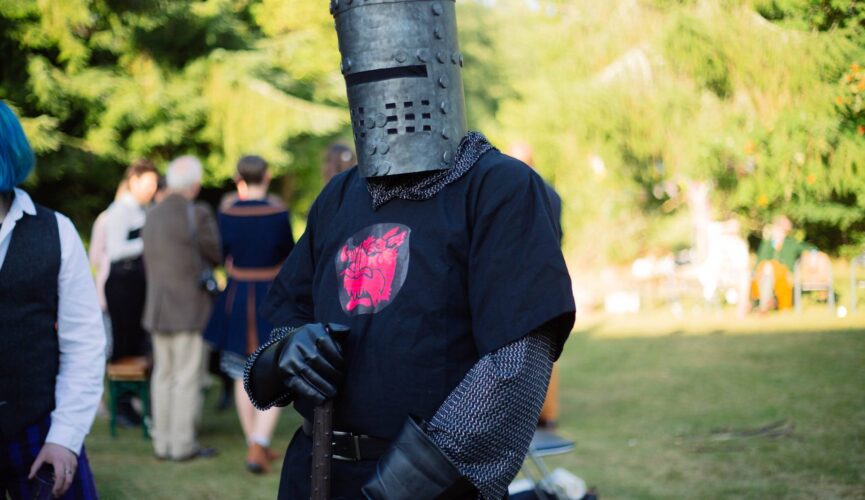
As a bonus, two friends of mine had a fancy-dress themed wedding a few months later on a bridge in a Scottish glen, and given a bridge in a natural setting the Black Knight cosplay was a must (despite the logistical challenge of getting it across the country intact).
With the lighting circuit and dice mounts successfully attached to the base layer, the final stage of creating the Infinite dGauntlet was to create the outer wrapping layer. For the design I took primary inspiration from the Nano-gauntlet in Avengers: Endgame, as this was closest to the Iron Man red/gold colour scheme that would fit best with Dungeon Master.
I used the same template I had created for the base layer, but added around 1cm of depth in order to add space for the circuit board and wiring, and added cut-out sections through which the dice mounts would protrude. Using the same black cotton fabric as a base, I used metallic red and gold spandex to build up the required design, using metallic thread which did not play well with the sewing machine at all.
Gauntlet wrist/palm outer layer pieces prior to assembly
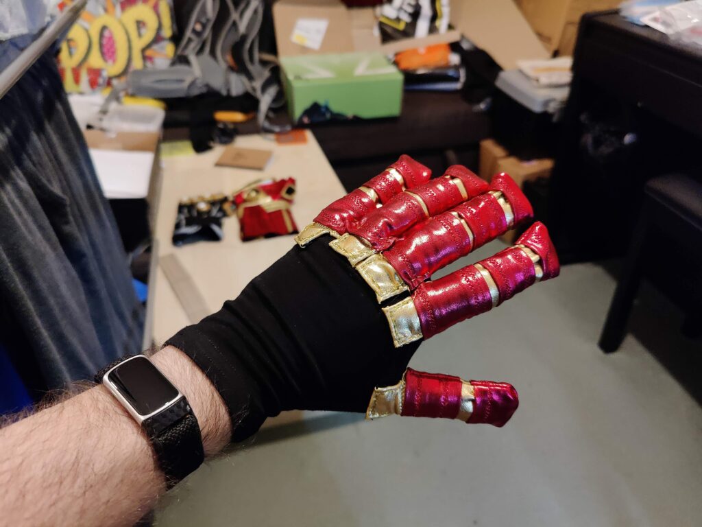
The fingers were similarly designed, essentially creating short tubes of fabric to be attached to a simple black glove that would be sewn inside the base layer.
Base layer and components of outer layer prior to final assembly
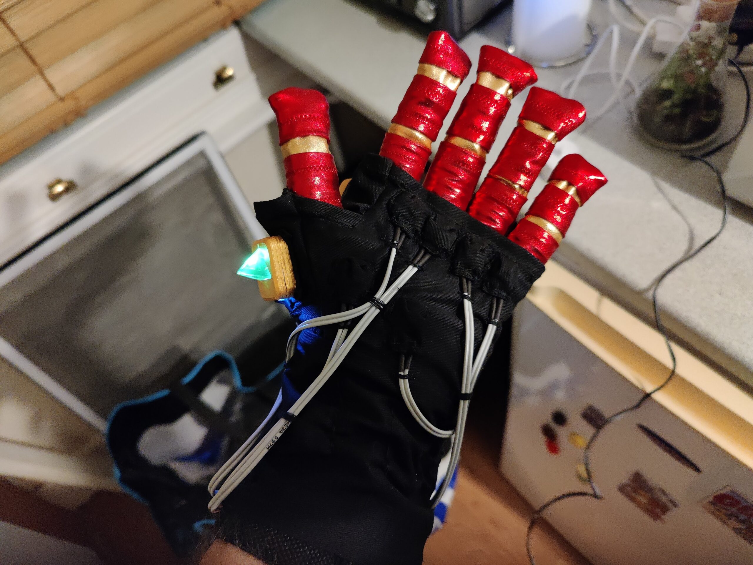
Fingers sewn and attached to the glove
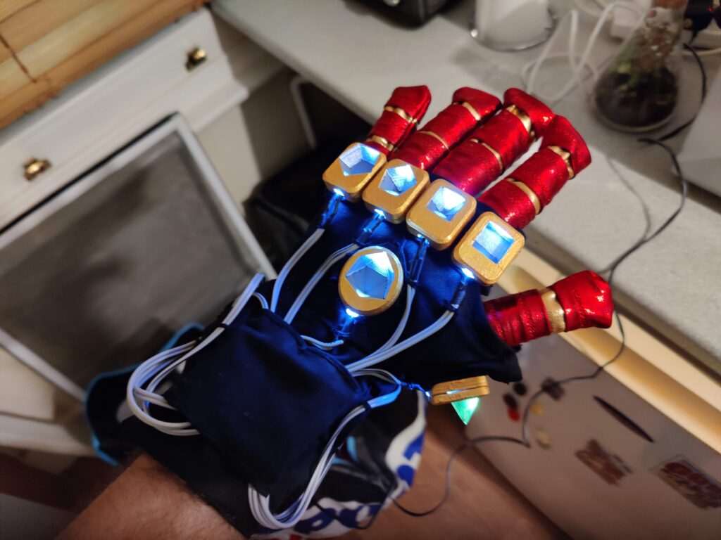
Glove sewn inside the base layerPalm switches
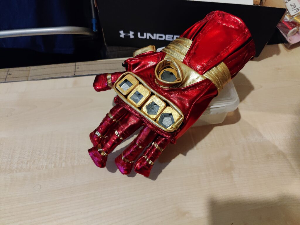
All that was left was to slip the outer layer wrist/palm section over the top and hand-sew the seams.
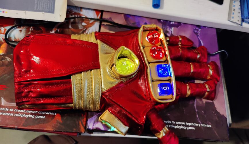
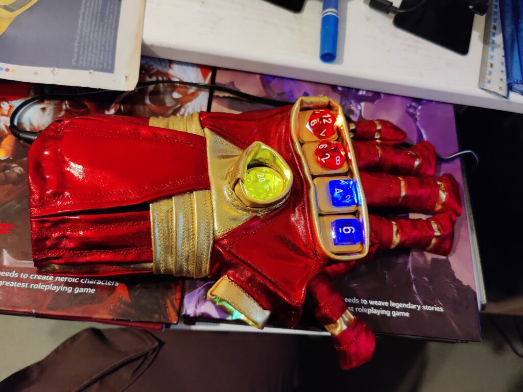
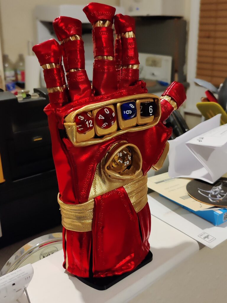
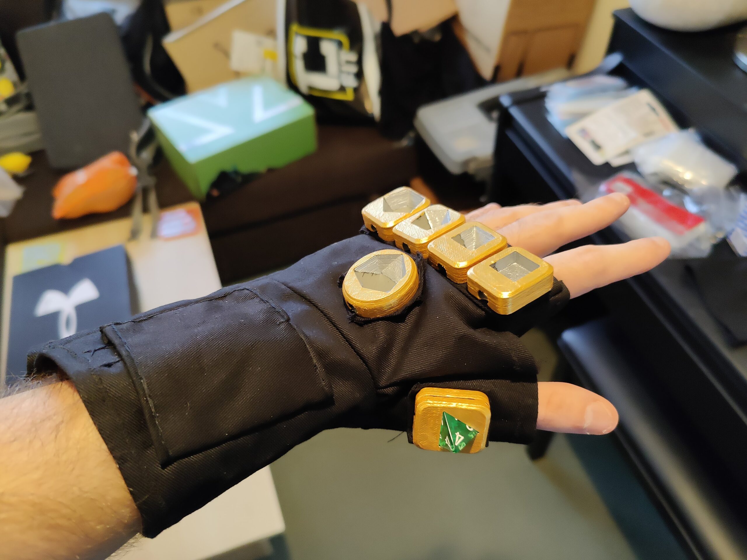
Completed gauntlet awaiting dice
The dice were then secured in their mounts using superglue to complete the Gauntlet.
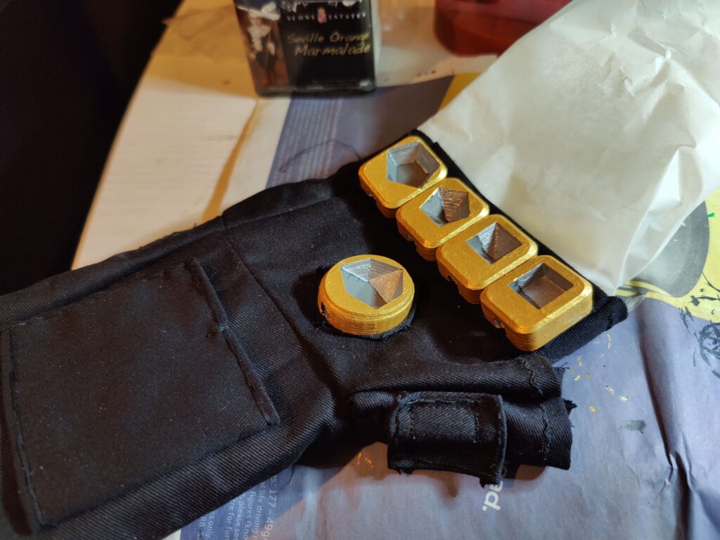
With the lighting circuit, dice mounts and base layer complete, it was time to bring them together. The first thing to do was to superglue the d4 into its mount, to avoid having to glue the two halves together later. Then I attached each mount to the relevant pad using superglue.
Used greaseproof paper to prevent any glue seeping through and sealing the wrap-around closedd4 mount attached
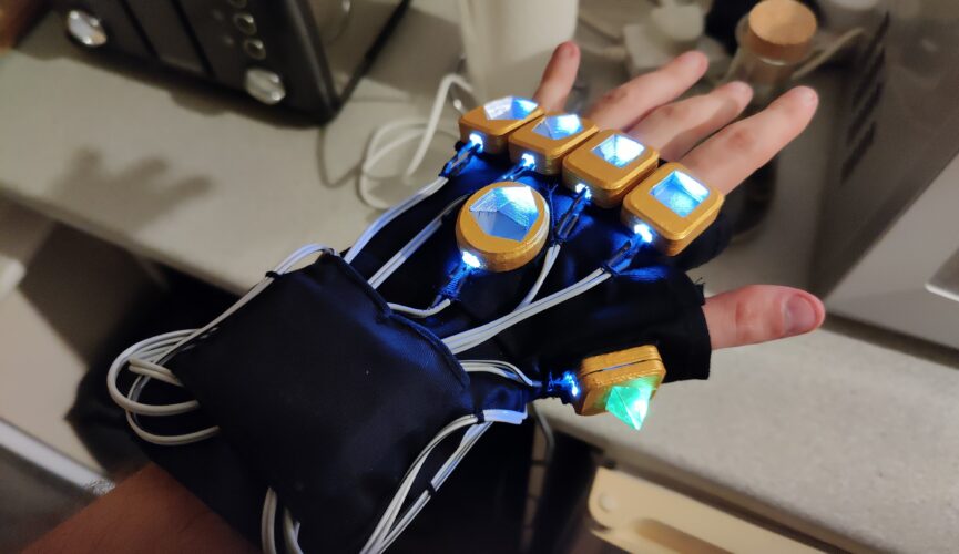
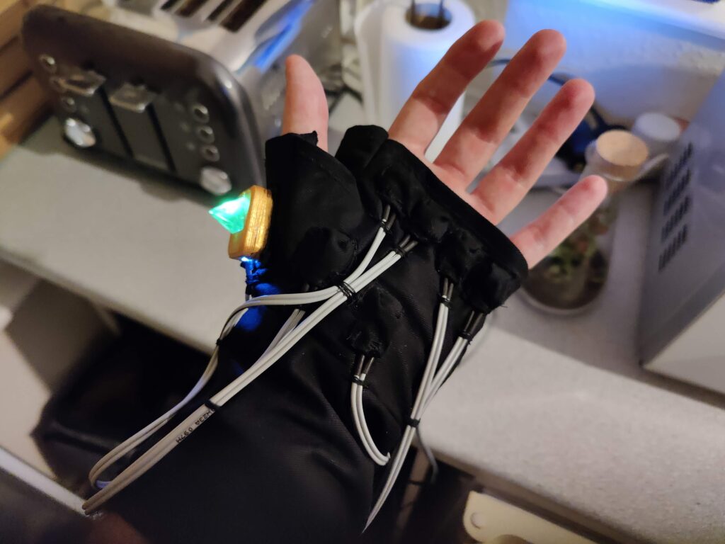
Attaching the circuit itself involved inserting the LEDs and sewing their cables in place. The tactile switches were sewn into their respective pockets, then the wires were fixed in position by sewing loops of thread.
LEDs with circuit board mountedTactile switches attached
I threaded the power socket through a button hole so it could be accessed from the inside of the wrap-around.
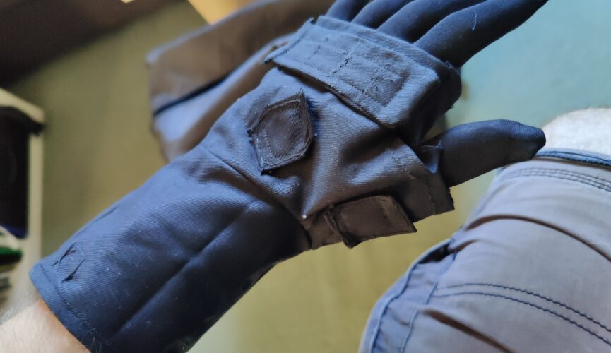
Gloves can be complicated, and my clothing design and manufacturing skills are limited. I had to work within what I could feasibly achieve, and having made a variation on an infinity gauntlet before (don’t ask) I decided to go with the approach I took last time: Use a standard glove to sew fingers onto, then sew that glove inside a wrap-around for the palm, which would essentially be a tube with an extra bit on the side for the thumb.
The wrap-around would consist of two layers:
An inner base layer, onto which the dice mounts would be glued and the circuit would be mounted (with hand sewing)
An outer layer, consisting of the actual visual design, with holes through which the mounts would protrude.
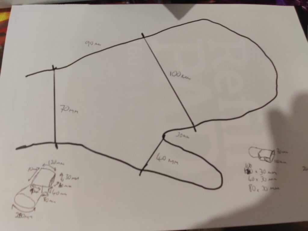
My approach to coming up with a pattern is very geometric, essentially approximate with a boxy design and hope the fabric’s tendency to curve will round it out. It’s also easier to think of a polyhedral net of flat faces rather than a more complex curved topology. The first step was, of course, to get measurements.
When in doubt, trace around it
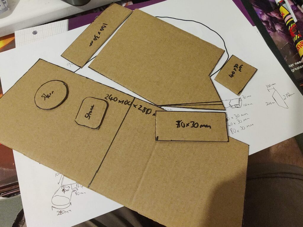
Pretty simple, trace around my left hand and use a ruler to roughly measure the notable lengths. Mark off where my knuckles and wrist were (roughly). Add a bit for ease of putting on/taking off, then create cardboard templates.
I also intended to add patches for the dice mounts, so I could be more exact when eventually attaching them.
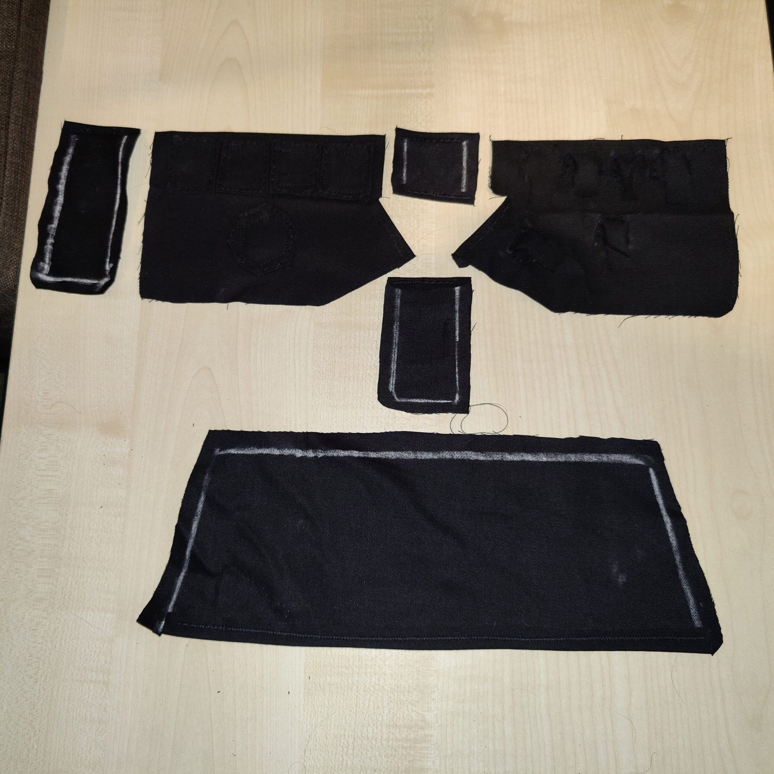
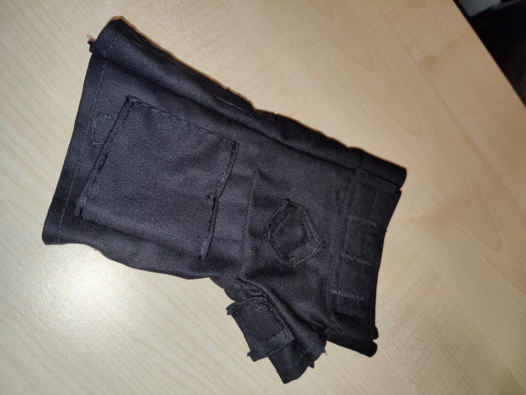
I transferred the templates to black cotton using chalk, which is a rather inaccurate method. I later got some wax pencils which worked a lot better.
With external edges hemmed
The first version was a little too tight to put on and take off, so a revised layer was made. I also decided to go with a single “bar” across the knuckles, with dividers sewn on top, instead of the individual stone pads I had originally used. This saved on complexity, and also supported the edges better which were a little wider than the finished glove layer.
Top sideUnder (palm) side
To the underside (where the palm will be) I added six miniature “pockets” for the tactile switches, each approximately 12x12x6mm in size.
With the glove inserted
I had actually made this prior to fabricating the circuit, so once I had a finalised size for the circuit board the last thing to do prior to assembly was to sew on a “sleeve” into which the circuit board would be secured.
With PCB sleeve
Simply a piece of fabric slightly larger than the board, with a notch sewn halfway across the top. Three of the LEDs would feed through either side, and the notch would prevent the board itself sliding through. Once inserted, I planned to sew a second notch in the bottom edge to hold the circuit board in place.
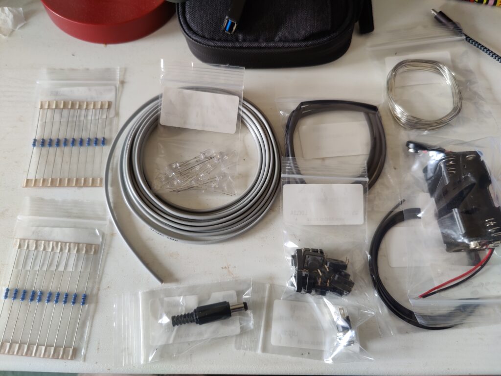
With the Printed Circuit Board (PCB) designed, the next job was getting it manufactured. Lacking the tools to do so myself, and having no experience ordering a PCB, this was a daunting prospect. Less daunting was sourcing the components for the circuit itself, with electronics components suppliers readily available online. I went with Bitsbox, a UK supplier whom over two orders were very quick to dispatch and deliver the components.
Bits!
The components ordered include:
10x 1K resistors
10x 330R resistors
10x 5mm Ultra-bright white LEDs
10x 12mm tactile push switches
2.1mm DC power socket
2.1mm DC power plug
1x 4xAA battery holder
1x 9V battery clip (connects to the battery holder)
3m speaker wire (3m additional in second order)
Heat-shrink sleaving
Solder
The speaker wire is essentially a pair of wires bound together, which would make managing the cabling easier. The particular wire I ordered was grey with a black stripe down one side, which made it easier to keep track of the circuit polarity (as LEDs, being diodes, only work in one direction).
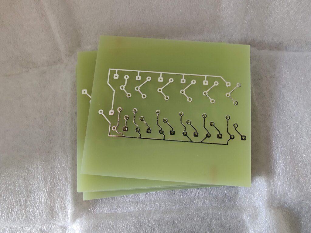
Trying to find a PCB manufacturer was difficult, as I am a hobbyist rather than someone looking to manufacture large batches of a given PCB. I initially tried to contact a few UK-based manufacturers, but with very limited success (as they seemed more set up for business-to-business interaction rather than making a small batch of custom boards). Looking to hobbyist websites it seemed that going to a Chinese manufacturer was the most cost-effective and easiest way to go, so I tried PCBWay. The interface seemed straight-forward enough to use and the pricing wasn’t astronomical, the only downside was I couldn’t get the extra holes drilled and the minimum batch order was 5. This wasn’t too much of an issue as having spares would be handy, and the PCB layout could work for any generic lighting circuit up to 6 LEDs so could be useful in future projects. Including delivery, I went from order to having the PCBs in hand in just over a week:
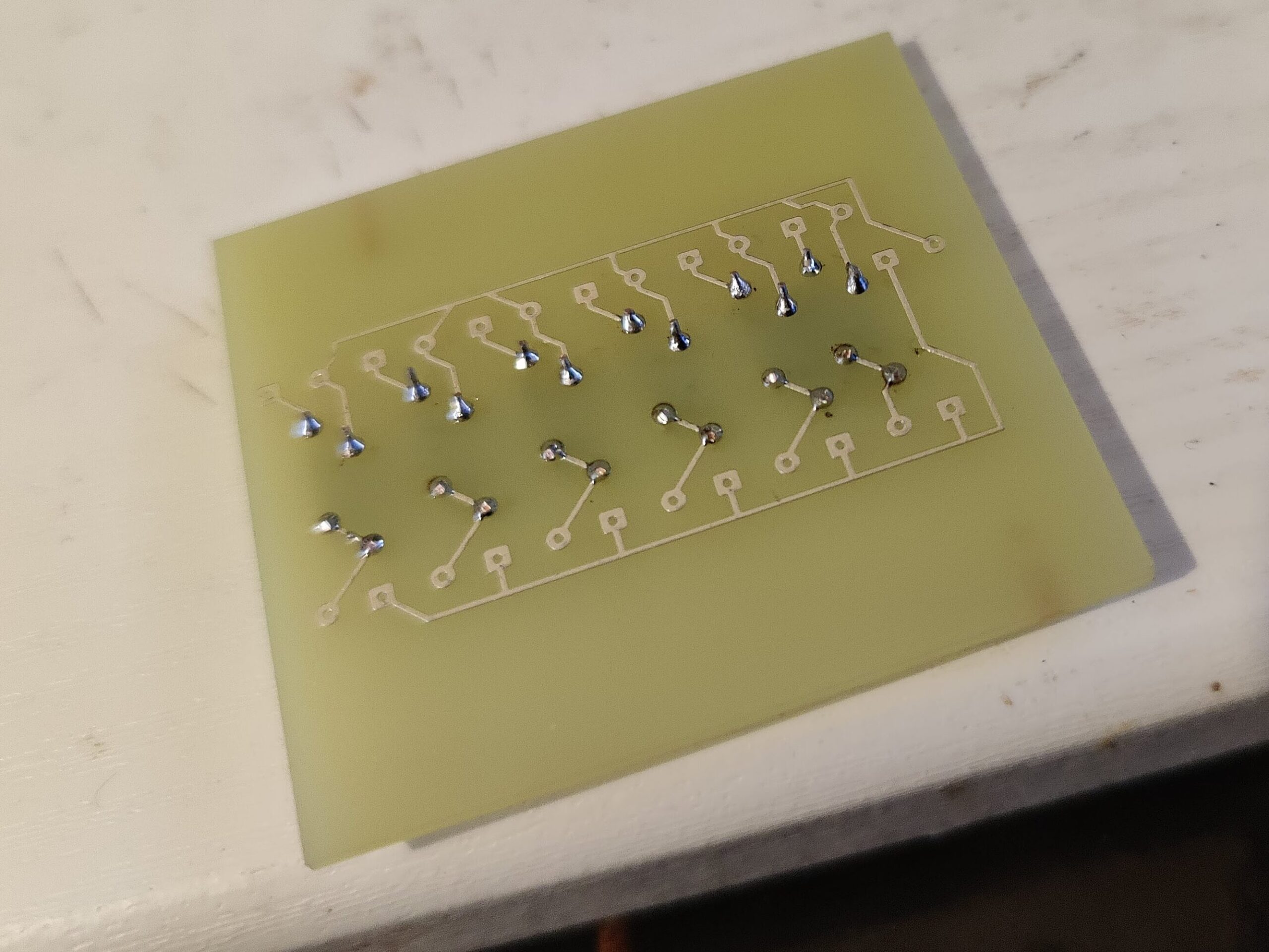
5 PCBs, minus all the extra holes
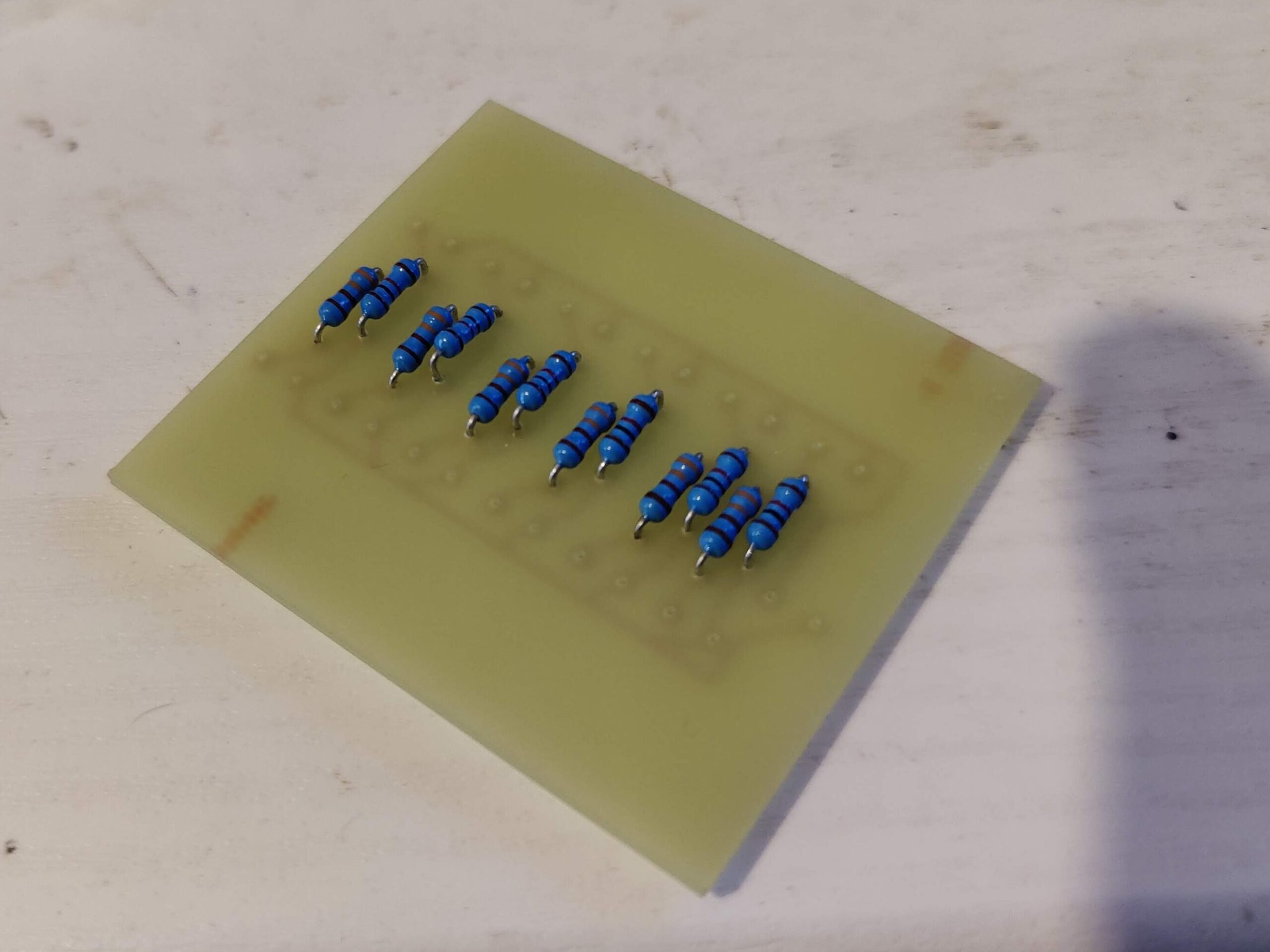
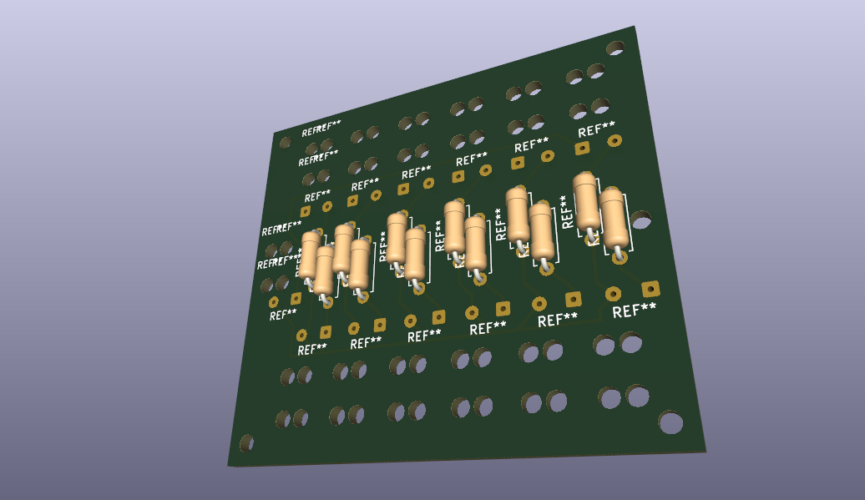
Lacking the ability (and skill) to drill the extra holes myself (the manufacturer did drill the holes in the circuit contacts), I figured the best thing to do was to solder the whole circuit together when the gauntlet’s underlayer was ready to have it installed, since once it was secured in place any stresses on the wires should be minimised. The first task however was to solder the resistors into place, which I could do right away.
I used to be pretty good at soldering back in secondary school, I think I’ve gone a bit rusty. Once soldered, I tested the circuit with a multimeter to make sure the solder joints were conducting current adequately.
The rest of the circuit involved measuring the approximate length of each wire needed, based on the planned route from the board to the component’s location on the gauntlet (either on the back of the hand or on the palm), adding a generous extra length (at least 10%) for losses when soldering, as well as a bit of room for placing the wires. (Better to have a bit too much cable than not enough).
The LEDs were relatively easy to solder, with long legs they’re designed to be soldered to wires or directly into boards. The main concern was ensuring I soldered the correct wire to the correct leg (I wanted to keep the wire with the black stripe as the positive/anode).
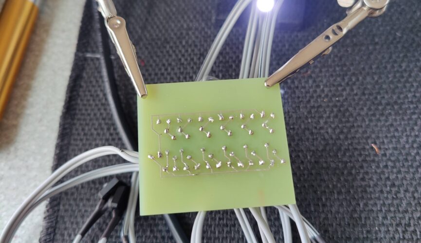
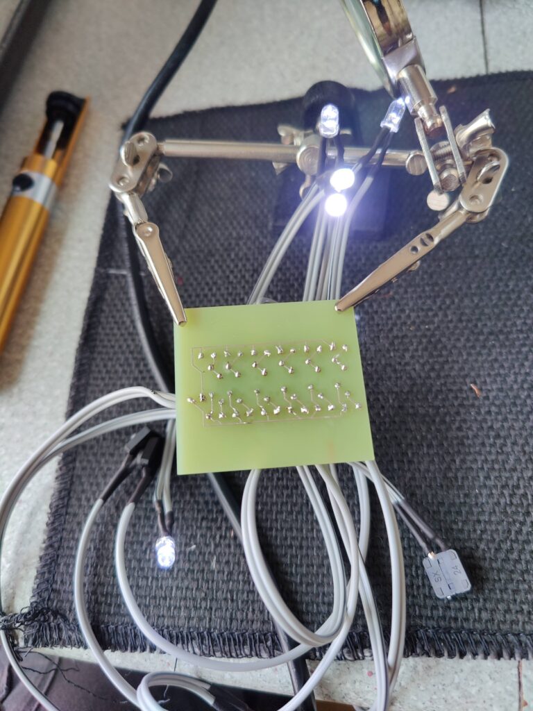
The tactile switches were a pain, since they are very much designed to be soldered directly onto a board, and not to wires. The tabs are very small and getting the wire to mesh with them enough to take solder was fiddly to say the least. The solder joints are far from the best I’ve ever done. But a few hours of work (with testing the circuit after each pair of LED/switch were added) thankfully yielded a successful result:
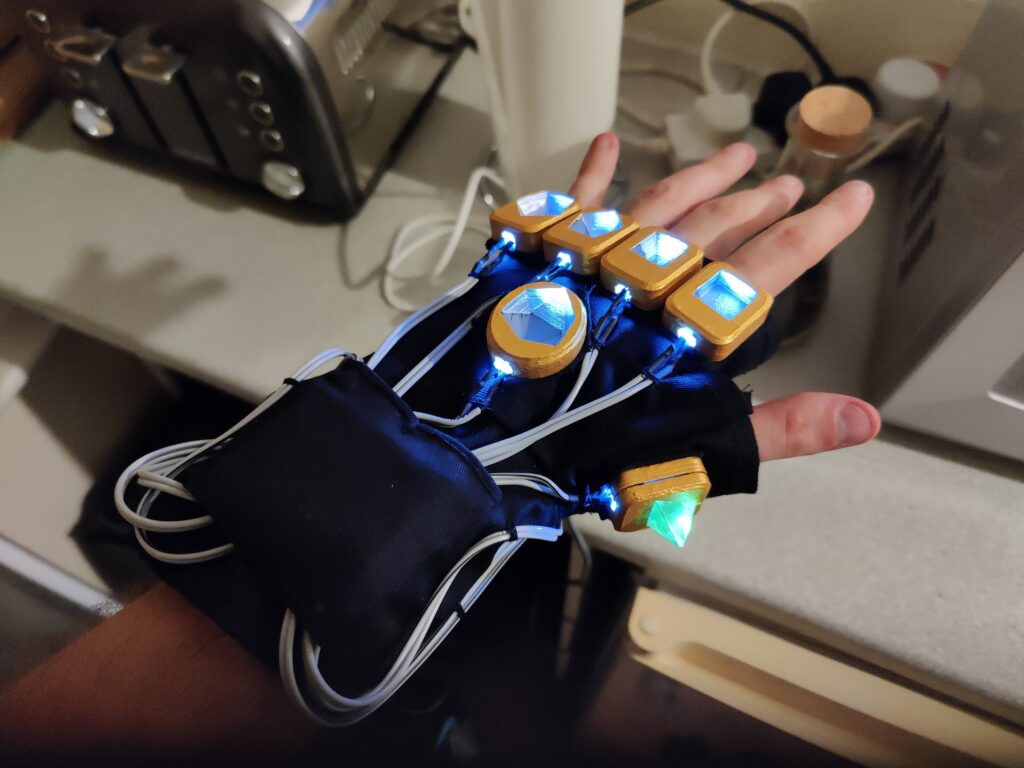
Lighting circuit, fully soldered.
Short demo of the circuit in action
Now with the lighting circuit made (and the gauntlet’s underlayer, which was ready by this point but I will document in a later post) it was finally time to bring it together…
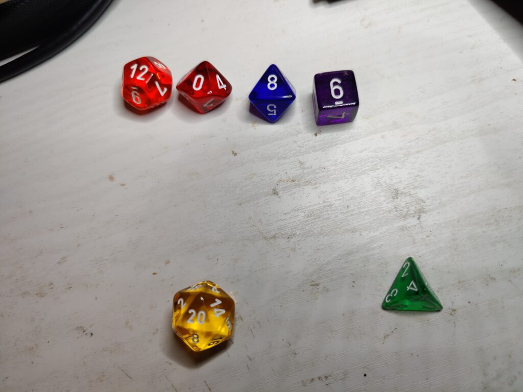
The most important components of the “Infinite dGauntlet” are, of course, the Dice themselves. Sourcing the dice was relatively easy, thanks to TheDiceShopOnline where I was easily able to select translucent dice in the appropriate colours:
Six coloured (math) rocks
Coming up with a means of securing these dice to a gauntlet, whilst at the same time incorporating a 5mm LED for illumination purposes would be incredibly difficult to do by hand. Fortunately I had a relatively new hobby to bring to bear: Enter 3D Printing! Before I could use a computer to solve all my problems, however, I had to get the measurements.
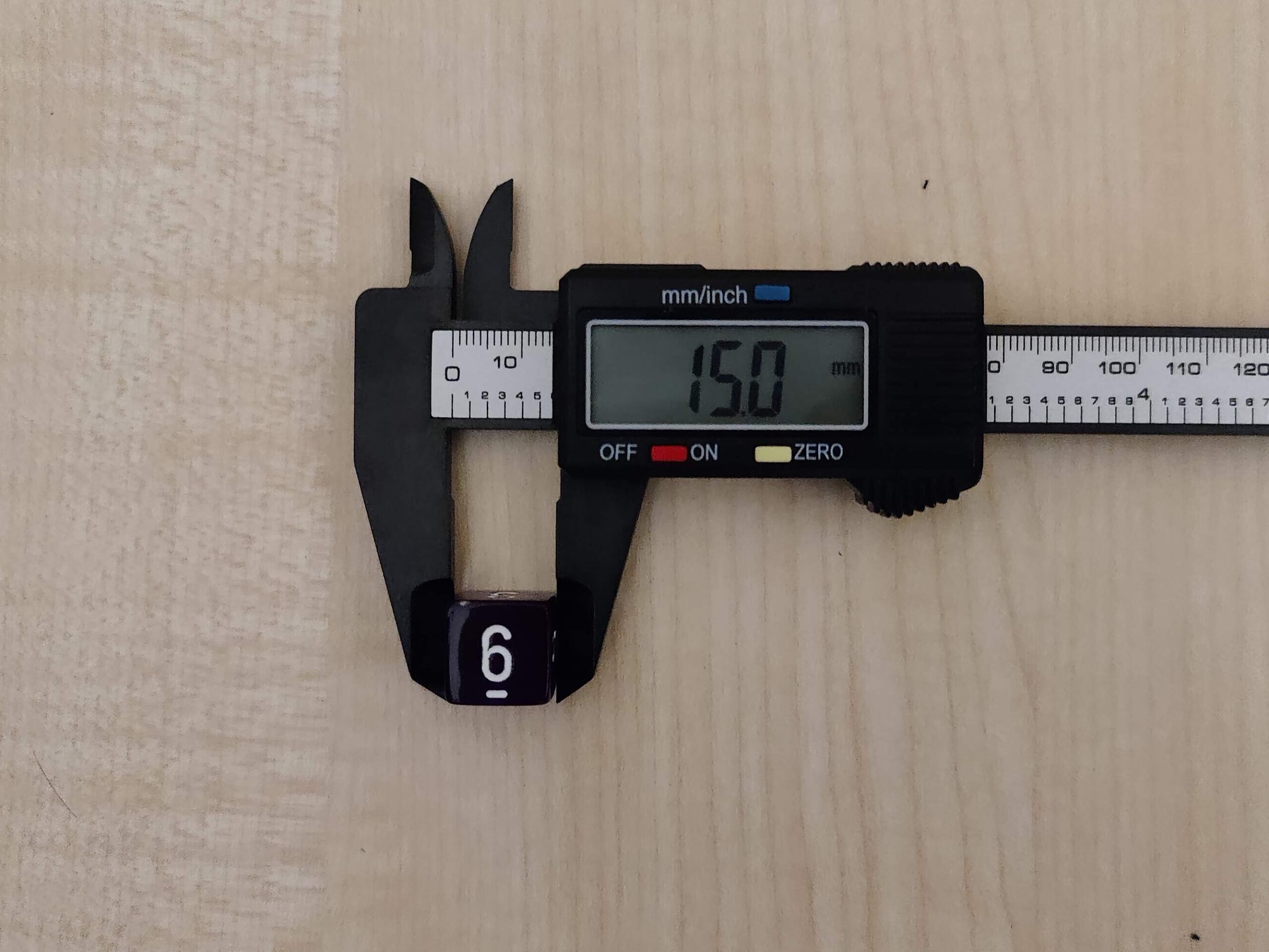
Measuring Dice… surprisingly fiddly, it turns out.
Questionably accurate measurements in hand, I downloaded Blender (a pretty good open-source 3D modelling software) and figured out how to kind-of work it in creating-STL-file mode. (The trick is figuring out how to set up the scene units, then how to set the correct scale factor when exporting.) The first step was to create a correctly sized “LED cutout” STL file I could then re-import and subtract in order to have a uniform insert for a 5mm LED.
A 5mm LED cut-out, with flared tip
Working out the external dimensions was a process of (roughly) measuring my left hand to figure out how wide a mount could be and still reasonably fit four across my knuckles. From there it was a case of estimating how large to make each one to fit a 5mm LED in addition to the half-dice, and figuring out the exact sizing within Blender by trying to fit everything together.
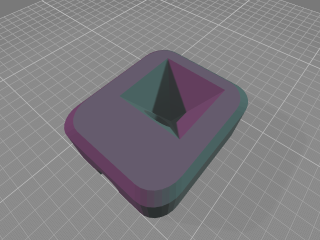
The d6 and d12 were the most straightforward, with the cube and dodecahedron being regular solids to use within Blender. A test-print of the d6 mount revealed the dimensions as measured were a bit tight, so I added around 10-15% to the measurements as I would eventually be gluing the dice in, and having them fit a little loose would be less of a problem than them being too tight.
Half a cubeThe bottom half of a dodecahedron
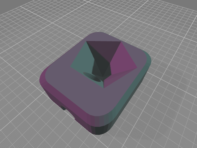
The d20 was similar, with an icosahedron not difficult to produce within Blender. It was slightly more complicated due to being the physically largest dice, but being set in the larger oval mount on the back of the palm:
Half of an icosahedron looks weird
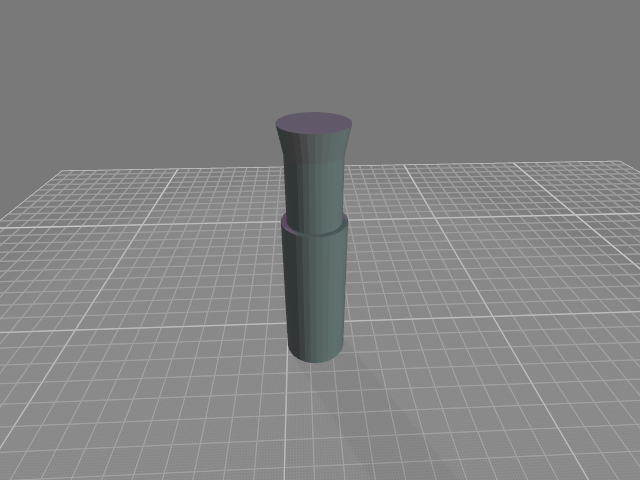
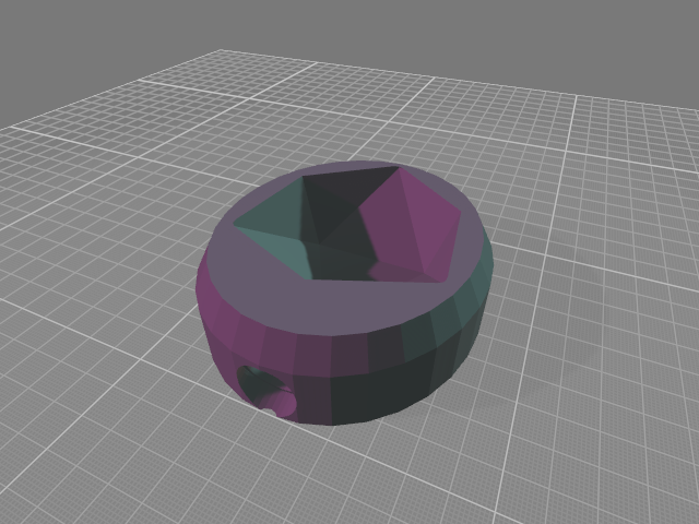
The d8 and d10 were slightly more complicated, but I reasoned they are both effectively two cones with their bases stuck together, each cone having half the total number of sides. So a 4-sided and 5-sided cone would fit each dice, and also hold them higher giving more room for the LED.
d8 “cone” mountd10 “cone” mount
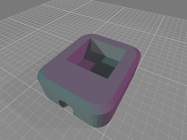
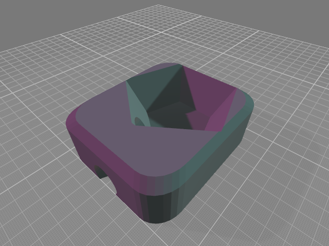
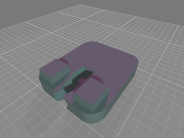
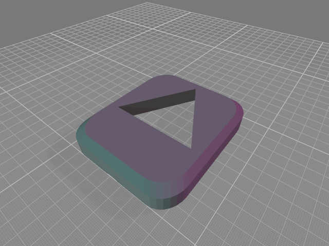
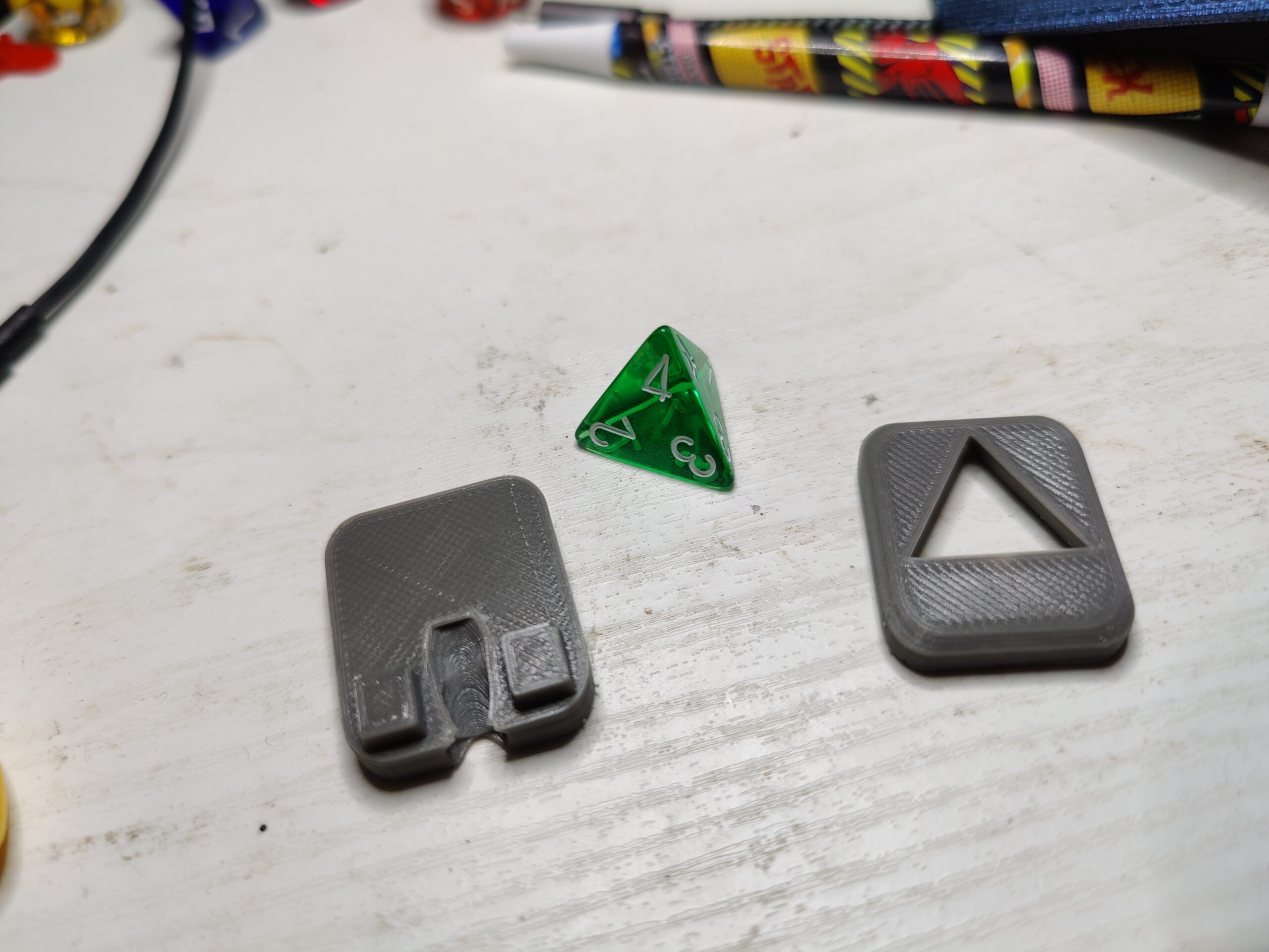
The d4, being a tetrahedron, was the most complex. I had originally thought of mounting it inverted, but that would mean the base of the dice sticking out as opposed to a given value. It would be possible to mount it in the “correct” orientation, but given its concave shape, it would require creating the mount in two halves, and gluing them around the dice:
The bottom half, with locator blocks.Top half, voids for the locator blocks on underside not shown
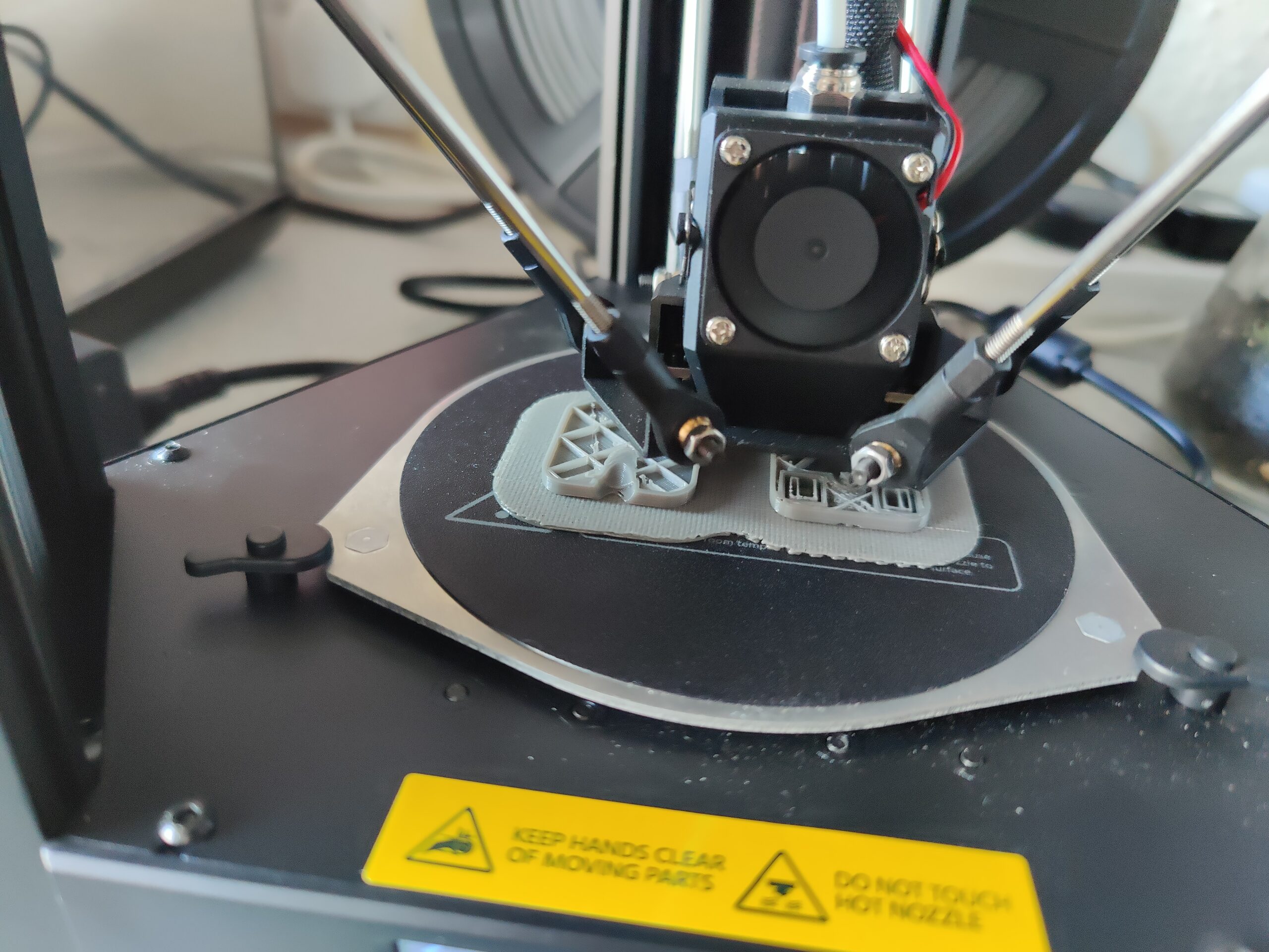
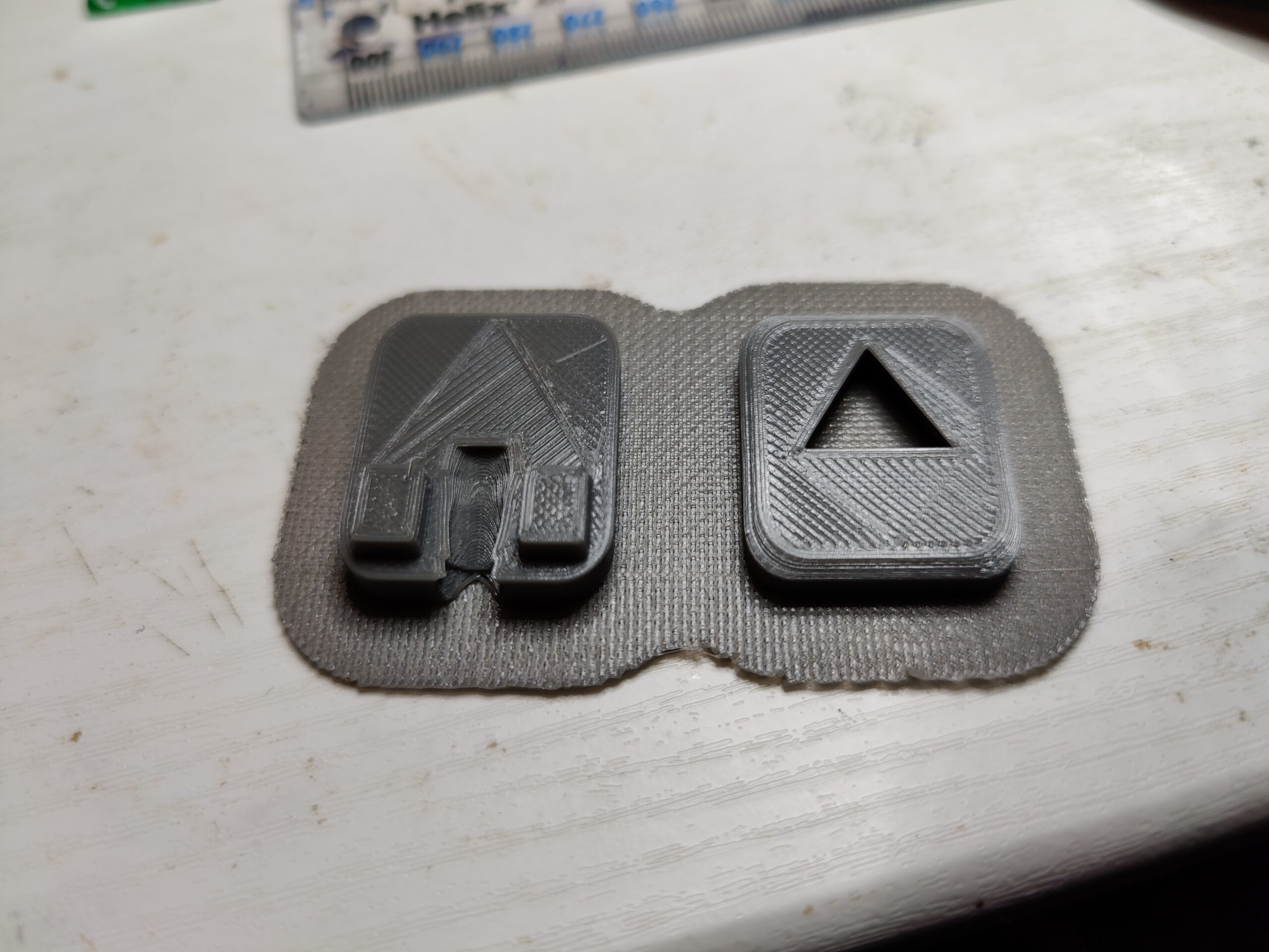
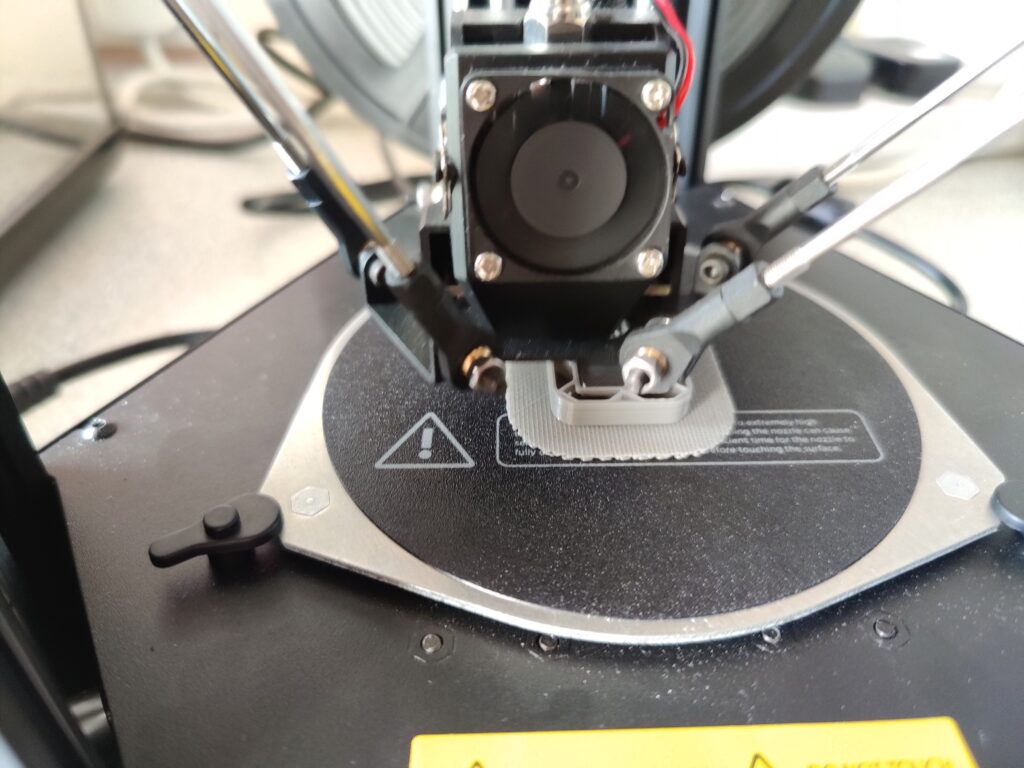
In reality, I went through the process of designing and printing these mounts one by one, adjusting and reprinting each as necessary. (The d4 required about 4 reprints to get the size right.) My 3D printer, a Monoprice Mini Delta V2, was able to print a mount in around an hour.
Printy printy…The printed mountRemoved from the base (fourth iteration)The final (fourth) attempt, with dice enclosed
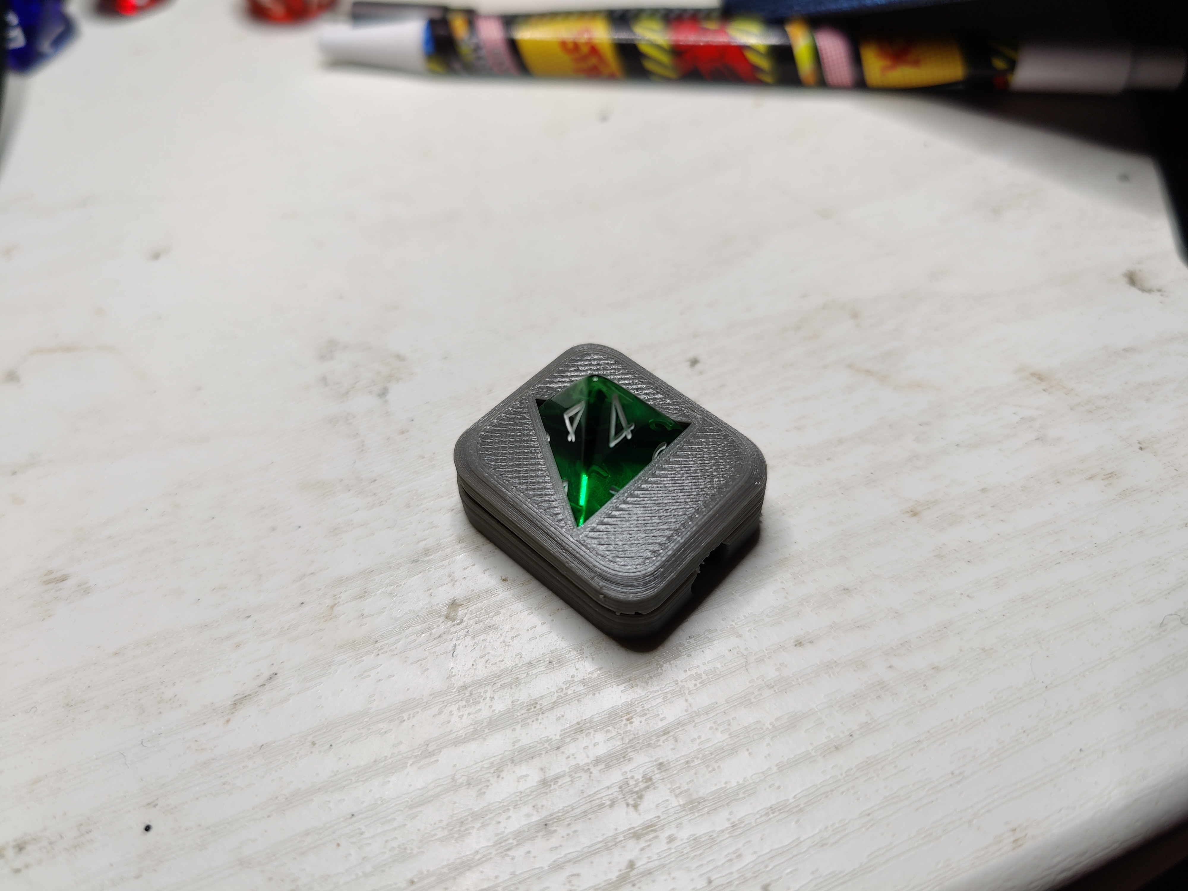
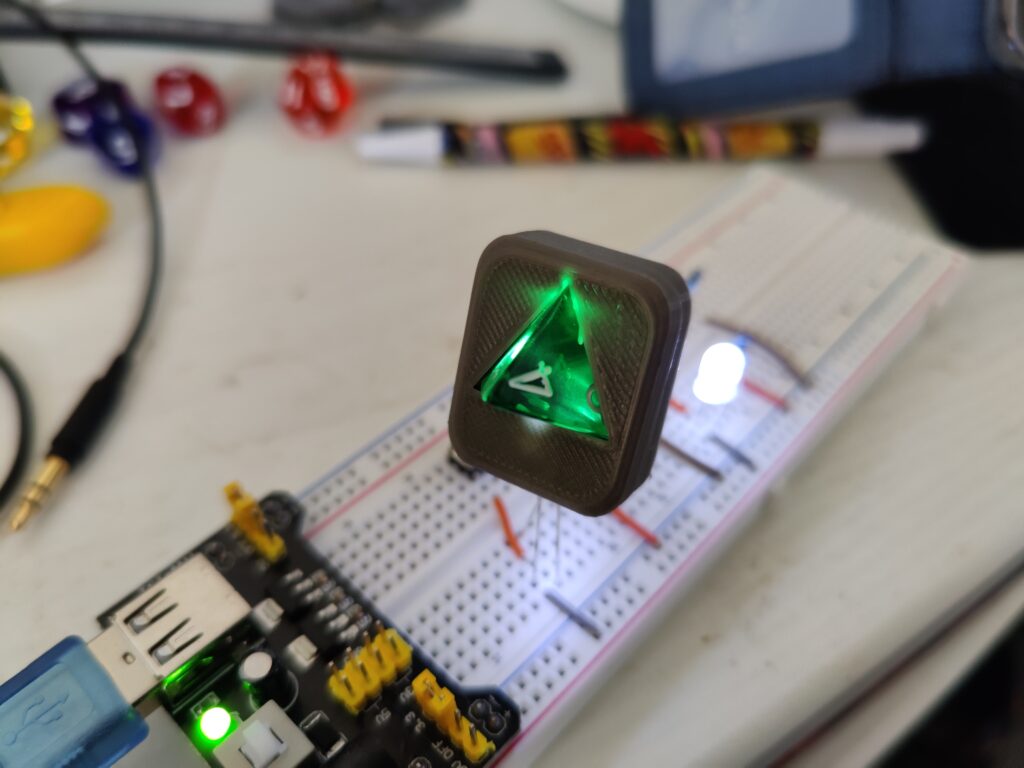
With the dice now fitting, I could test the fit for the LED. (The LED cutout seemed to work first time, given the manufacturing tolerances of a 5mm LED I suspect it was my measurements of the dice that were lacking.)
With dice and LED enclosed
With the d4 mount complete, I focused on the rest:
Printing the d6 mount
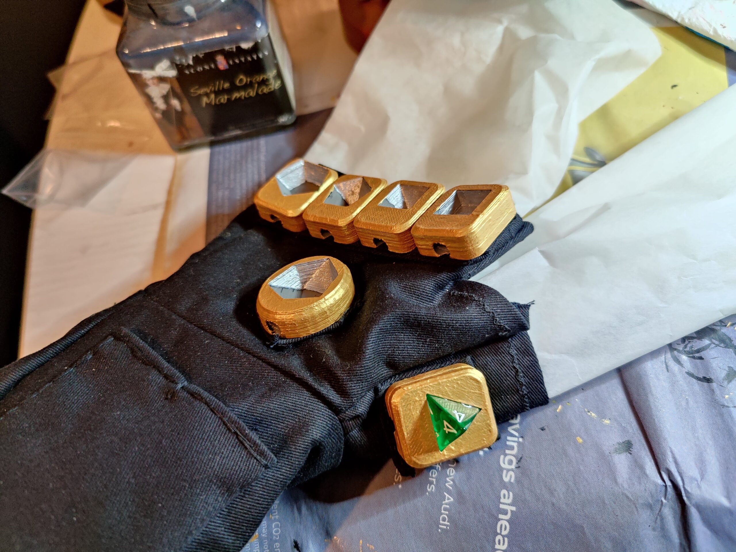
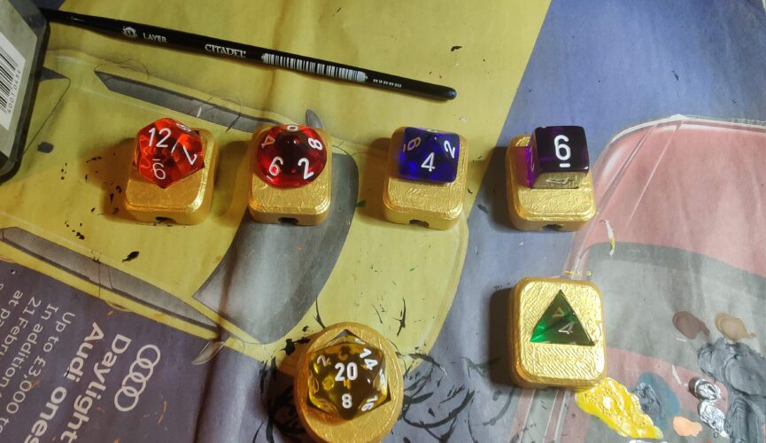
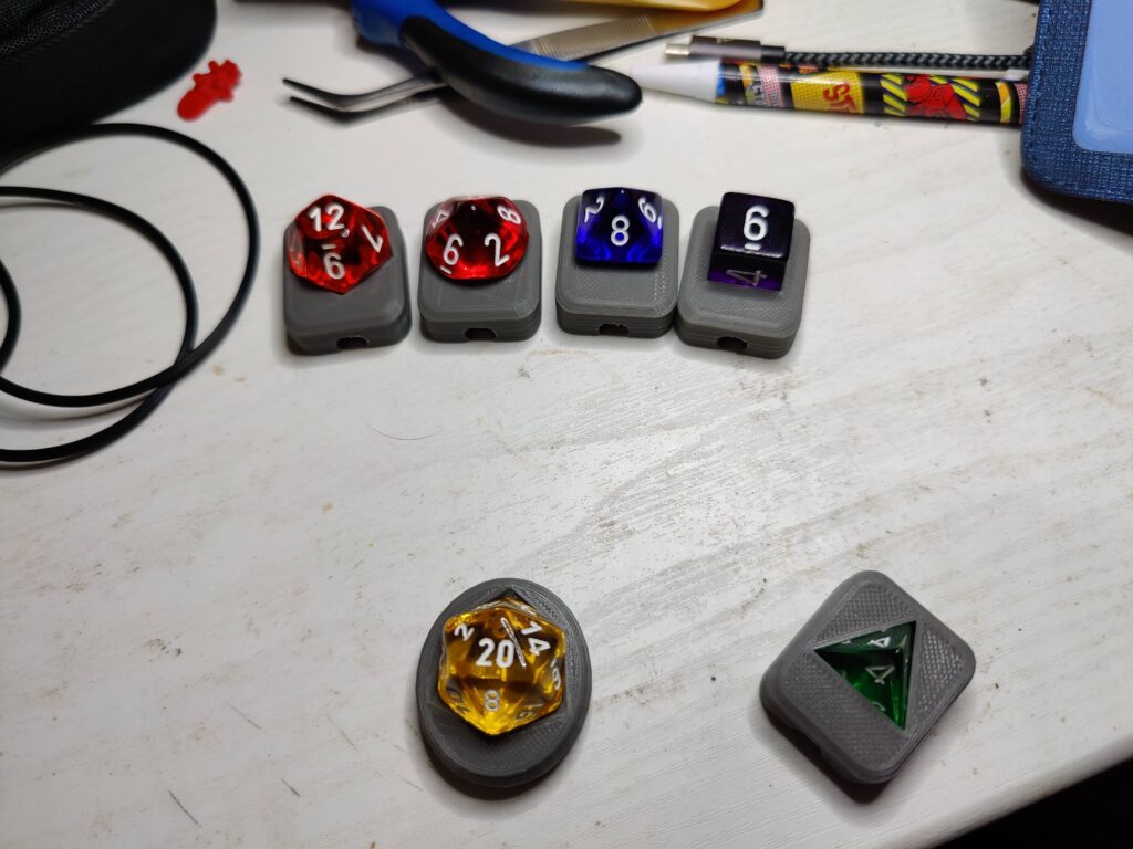
The mounts with their dice
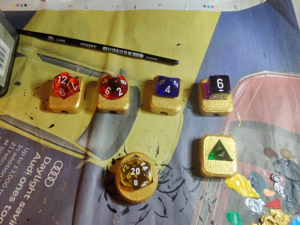
Final thing to do was add a coat of gold paint, and a bit of silver inside in an attempt to act as a foil to reflect light back through the dice:
When conceiving the idea for what I’m loosely calling the “Infinite dGauntlet” a number of ideas came to mind. The “ideal” functionality and look that I would aim for, and the levels below that I could achieve if resources/time became too much of a constraint. The ideal in this case would be individual illuminations for each dice, and the ability to selectively brighten any/all of the dice by the action of closing the fist. Failing that, illuminating the dice would be a more achievable goal.
5mm Ultra-bright White LEDs seemed an obvious choice, they would likely be small enough to fit inside a 3D-printed mount for each dice yet powerful enough to provide sufficient illumination. For control, a few options came to mind. Reed switches combined with magnets sewed into the fingertips might have worked, but with a number of the switches in close proximity it may have been difficult to selectively activate them. I eventually decided the simplest option would be some variety of tactile push-to-make switches, generally flatter I figured they would quite easily be sewn into the gauntlet.
So the question arose: How to use a push-to-make switch to make an LED brighter when pushed? A brief bit of research on LED brightness (googling and answer on StackExchange) unearthed the fact that LED brightness is roughly proportional to the current flowing through it. Remembering Ohm’s Law from secondary school:
Where V is Voltage, I is current and R is resistance
The plan for the circuit is to run on 4xAA batteries, so the voltage across the LED will be fairly constant. This means Current will be inversely proportional to resistance.
The second piece of the solution comes from how components of a given resistance (namely resistors) combine. In series, resistances combine by simple addition, but in parallel it is their inverses (or conductances) that add together:
Essentially this means that two resistors in parallel have a total resistance that is less than either resistor individually. This means I could place a push-to-make switch alongside a second resistor, both connected in parallel with the first. Then when the button is pushed, the resistance of the entire segment is reduced, the current increases and the LED shines more brightly.
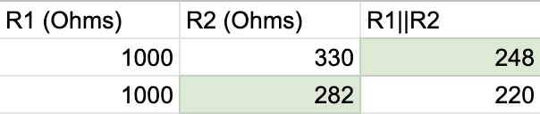
Given my knowledge from secondary school electronics, I recall we would always use a 220 Ohm resistor with LEDs, so figured that was a reasonable lowest resistance/highest current for the “active” higher illumination state. I wanted there to be a noticeable difference between the two states, so went with a 1,000 Ohm resistor for the inactive state. Knowing the desired total resistance and value of resistor R1 figuring out a suitable R2 was relatively straightforward:
Green cells are the Output
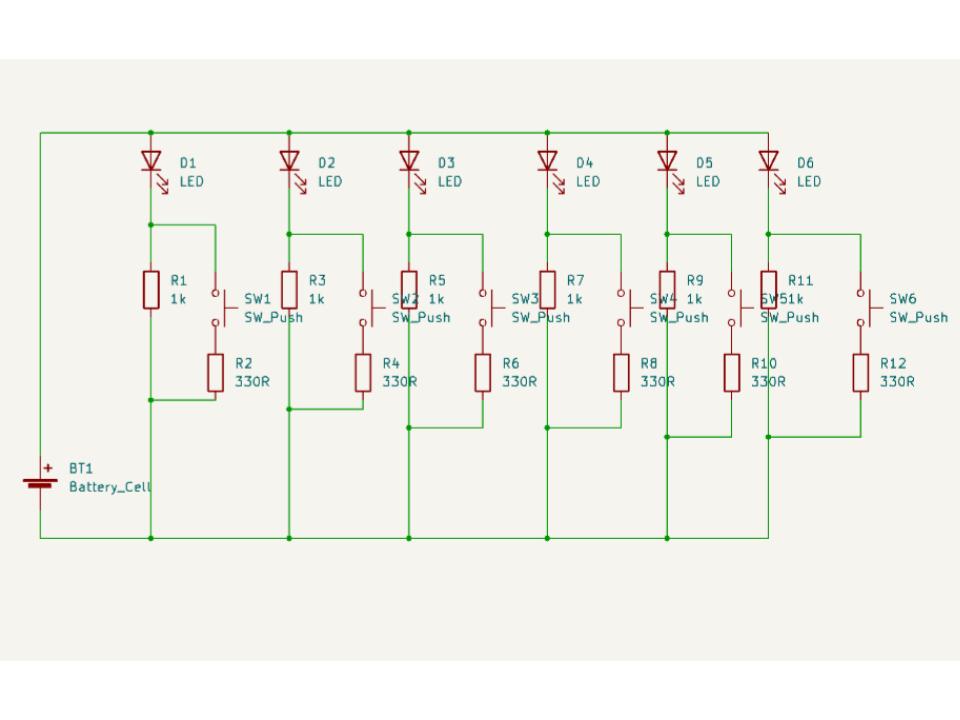
The exact R2 I would need was 282 Ohms, but 330 Ohms (a more standard fixed resistor value) got me to 248 Ohms, which was close enough. So the basic unit of the circuit would involve an LED and 1 Kilo-ohm resistor, always connected, with a second 330 Ohm resistor and switch in parallel with the 1 Kilo-ohm resistor. Multiply that by six for each light, and the circuit diagram looks something like:
A circuit, courtesy of copy-and-paste
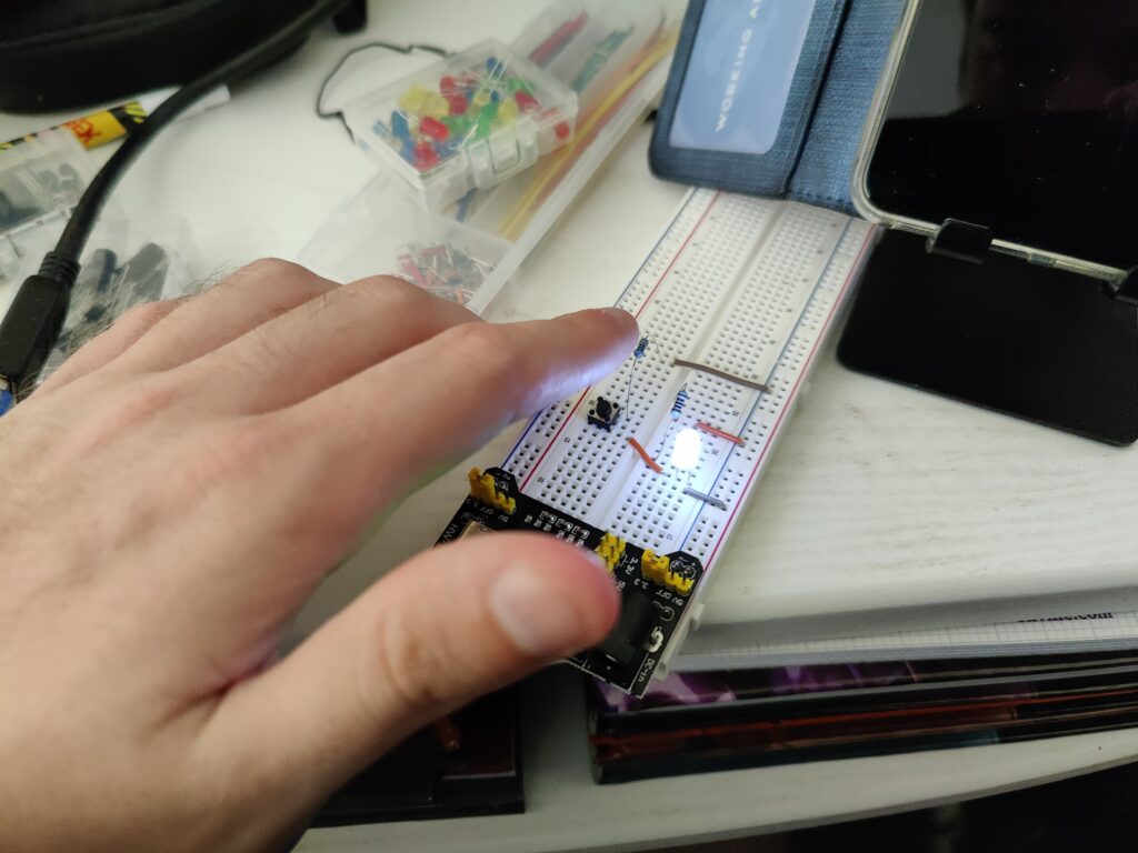
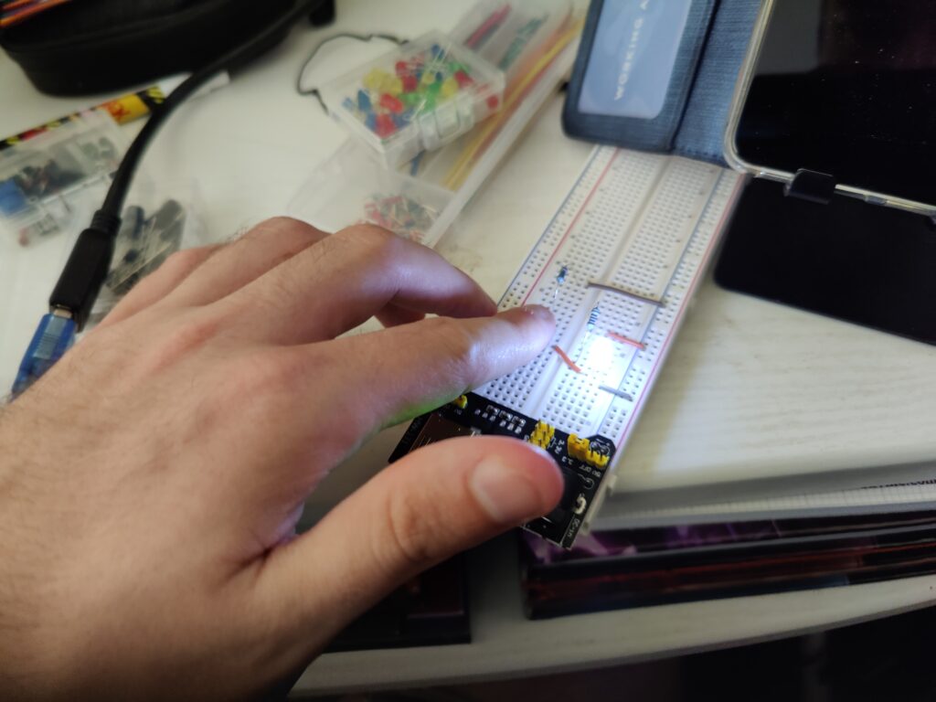
All good in theory, but before I want to the trouble (and expense) of turning this into a circuit board I wanted to be sure it would actually work. It was finally time for me to get myself a breadboard. I found this kit on Amazon for a reasonable price and quick delivery, and before long I had wired up a prototype.
Button OffButton On
With the circuit figured out, the next task was transferring it to a Printed Circuit Board layout. Once again my experience from school was limited, the software we used (which I cannot remember the name of) was fairly basic. KiCad seemed to be the best open source software for designing PCB layouts, though it has something of a learning curve. (Multilayer PCBs, solder masks and a whole catalogue of component footprints.) However I managed to figure out enough to lay out the circuit I needed. The main challenge was figuring out a design that would be small enough to fit into the gauntlet, but not so small as to be too difficult to solder together. With six LEDs and six tactile switches, as well as a power input, there would be 13 pairs of wires to attach which seemed like it would be too crowded, but this is what I eventually came up with:
The 3D Circuit Visualisation provided by KiCad
The holes were intended as mounting points for the board as a whole, as well as a means by which to secure the wires. In secondary school electronics we would thread a wire through larger drill holes in the PCB before soldering, as doing so meant any forces on the cable wouldn’t be directed into the solder joint, which can be brittle and break easily. I wasn’t sure whether I could find a manufacturer who could drill the holes as specified, or indeed if holes so close together were even feasible for the board material. However if it wasn’t possible I had planned to secure the wires to the gauntlet itself so, once installed, stresses on the solder joints should be minimal.
Now all that was left to do was order in the components and try to get the board manufactured.
Now that conventions have returned since the disruption of the COVID-19 pandemic (thoughts as to whether this is wise aside) it would seem inevitable that my costume-making itch would demand to be scratched. I attended Destination Star Trek in November 2021 (with costumes I had created prior to 2020), subsequently caught COVID just in time to spend Christmas in isolation, then attended MCM London Comic Con in May of this year, albeit not in costume.
Not long after my thoughts turned to what ambitious and ill-conceived idea to attempt for the following MCM at the end of October. Having delved further into another of my hobbies/all-consuming time-sinks: Dungeons and Dragons, my sets of math-rocks were never far from my desk, and the process of world-building never far from my mind. The thought inevitably occurred to me that the standard set of dice used for D&D consists of seven dice. If one ignores the duplicate d10 used as part of the d100, there are six fundamental dice: The d4 (tetrahedron), d6 (cube), d8 (octahedron), d10 (pentagonal trapezohedron), d12 (dodecahedron) and d20 (icosahedron).
Ever a fan of the Marvel Cinematic Universe, the concept of six “stones” that can manipulate reality conjured the obvious thought of the Infinity Stones and Thanos, the imposing and brilliantly executed grand villain of the MCU’s 20+ movie-spanning infinity saga. The thought of doing a crossover/fusion cosplay has appealed to me for a while, the creative freedom to try and merge different characters into something that has no canonical “correct” answer. (Though I’ve always considered my standard for costuming to be “can you tell what I’m trying to be?”) So I could hardly resist the temptation to try:
“With the power of these stones… reality can be whatever I want…”
The Dungeon Master (from the Dungeons and Dragons animated TV show) crossed with Thanos (from the MCU). Unfortunately I couldn’t come up with a good portmanteau of the two characters’ names, so the working title I’ve gone with is “DMos”. The red/gold colouring of Dungeon Master also lends itself a bit to Iron Man, so I am mixing in some of that to try and blend the two together. (Specifically I am attempting to model the gauntlet after the Nano-Gauntlet in Avengers: Endgame.)
The plan is for this costume to incorporate a lighting circuit for the gauntlet. Whilst I managed to wire up some LEDs for my first cosplay (Cyberman, 2016) that was a very basic hand-soldered mess. With six LEDs and (hopefully) the ability to adjust the lighting level individually (to “activate” a given dice) a printed circuit board was going to be a necessity. Though I have some experience with designing/creating PCBs from secondary school, I’ve considered designing/acquiring and assembling the lighting circuit to be a “new” skill I’m effectively re-learning for the purposes of this project.
Another aspect of this project is working with metallic-effect fabric. A bit of internet research led me to spandex, seemingly the most cost-effective metallic fabric I could easily source. Being a stretchy fabric that I haven’t really worked with before I’ve considered this a new skill as well.
This project will also be the first opportunity I’ve had to incorporate 3D printing, another hobby I have recently dabbled in, into a costume project.
As of the time of writing I have been working on the project on-and-off for a few months, so the next few posts will be catching up to where I currently am. But with only a few weeks until MCM and a lot of the costume still left to make it is far from certain I will make the deadline.


![\[ V = IR\]](https://cosplay.danielsmedley.com/wp-content/ql-cache/quicklatex.com-2ad3b298d8156a7868110630d6443d9d_l3.png "Rendered by QuickLaTeX.com")
![\[ \frac{1}{R_{T}} = \frac{1}{R_{1}} + \frac{1}{R_{2}} + \dots + \frac{1}{R_{n}}\]](https://cosplay.danielsmedley.com/wp-content/ql-cache/quicklatex.com-372d01ab73b5e25e5b2d8761730202b2_l3.png "Rendered by QuickLaTeX.com")